Triangular positioning system and method based on visible light
A technology of triangulation positioning and visible light, which is applied in positioning, radio wave measurement systems, measuring devices, etc., can solve the problems affecting ranging and positioning accuracy, lack of accurate and operable light incident angle measurement methods, difficult signal synchronization and time measurement and other problems, to achieve the effect of convenient synchronization and control, and simple hardware
- Summary
- Abstract
- Description
- Claims
- Application Information
AI Technical Summary
Problems solved by technology
Method used
Image


Examples
Embodiment Construction
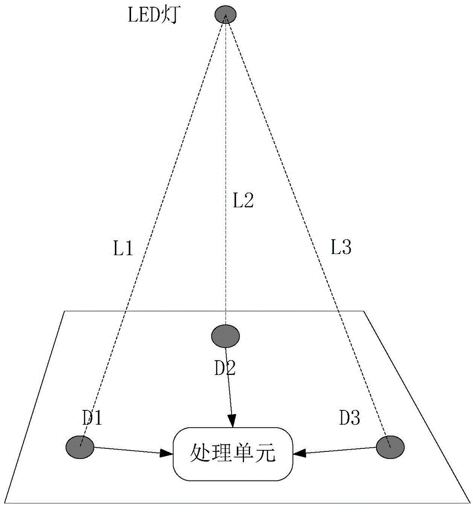
[0017] The present invention will be described in further detail below in conjunction with the accompanying drawings and embodiments.
[0018] Such as figure 1 As shown, the target to be positioned uses LED lights to send visible light signals, and at the signal receiving end there are at least three photodetectors with known coordinates to receive the light signals from the LED lights at the same time. figure 1 Among them, D1, D2, and D3 are three photodetectors distributed unevenly. The sending frequency of the LED lights at the sending end is ω 1 , the initial phase is q 1 The sine wave of sin(ω 1 t+q 1 ). There are two different optical detectors D1 and D2 at the receiving end, and the optical signal received by D1 is expressed as: S 1 =A 1 sin(ω 1 t+ω 1 t 1 +q 1 ), where A 1 is the gain, t 1 is the transmission delay of the optical signal to the photodetector D1. The optical signal received by the optical detector D2 is expressed as: S 2 =A 2 sin(ω 1 t+ω ...
PUM
 Abstract
Description
Claims
Application Information