Power pack system and power pack system optimization method
A technology of a power pack system and an intelligent system, applied in the field of power pack system and power pack system optimization, can solve the problems of long adjustment time, the operation efficiency of the cooling system cannot be in an optimal state, and the matching cannot be optimized.
- Summary
- Abstract
- Description
- Claims
- Application Information
AI Technical Summary
Problems solved by technology
Method used
Image

Examples
Embodiment 1
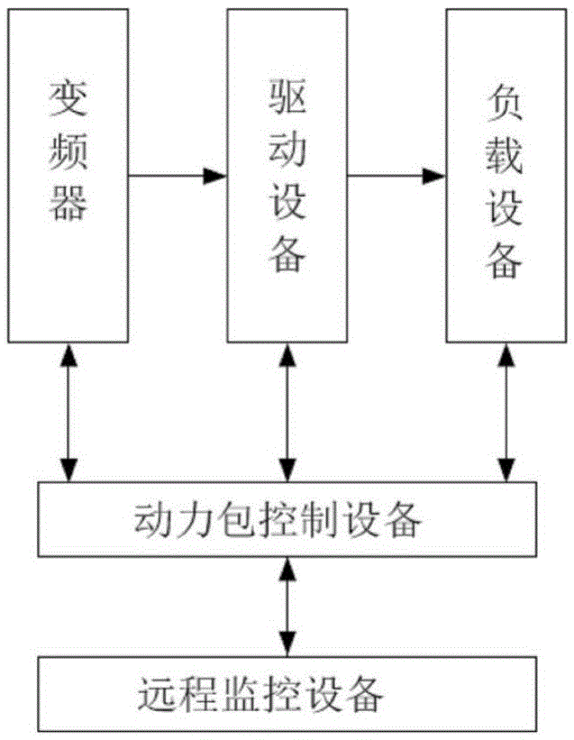
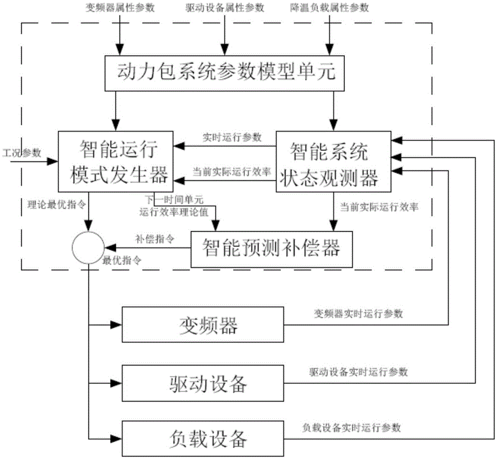
[0048] figure 1 It is a schematic structural diagram of the power pack system provided by Embodiment 1 of the present invention, figure 2 yes figure 1 Schematic diagram of the structure and connection relationship of the power pack control equipment; Figure 1~2 As shown, this embodiment provides a power pack system, which can be applied to the factory pipe network cooling system of a power plant, and can specifically include:
[0049]The load equipment can be used as the execution equipment of the power pack system to cool down the heat source in the power plant; for example, the load equipment can be large fans and / or condensate pumps and / or compressors and other equipment in the power plant .
[0050] The driving equipment can be connected with the above-mentioned load equipment through the transmission equipment (such as bearing transmission system, etc.) to drive the load equipment to work; Electric energy is used to drive the above-mentioned fan and / or condensate pu...
Embodiment 2
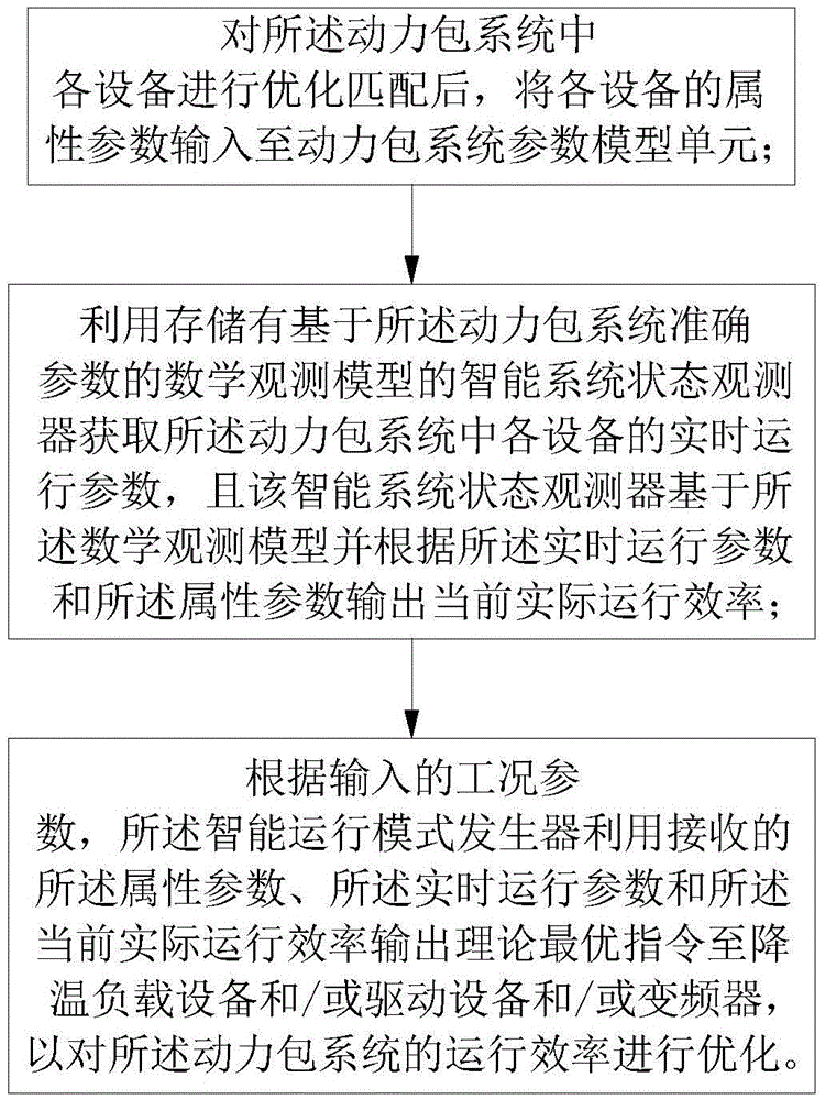
[0066] image 3 It is a flow chart of the power pack system optimization method provided in Embodiment 2 of the present invention. The power pack system optimization method in Embodiment 2 can be based on the power pack system in Embodiment 1 above (that is, the power pack system in Embodiment 1 and Embodiment 2 The same or corresponding technical features can be applied to each other), which can be applied to the cooling of heat sources in power plants, such as Figure 1~3 As shown, the above-mentioned power pack system optimization method may include:
[0067] First, after optimizing and matching each device in the power pack system, input the attribute parameters of each device into the power pack system parameter model unit.
[0068] Secondly, the real-time operating parameters of each device in the power pack system can be obtained by using an intelligent system state observer that stores a mathematical observation model based on accurate parameters of the power pack sys...
PUM
 Abstract
Description
Claims
Application Information