
Electron supply system

An electronic supply and electronic technology, applied in the direction of circuits, discharge tubes, electrical components, etc., can solve problems such as covering ion beams

Active Publication Date: 2016-04-06
北京凯世通半导体有限公司
View PDF3 Cites 0 Cited by
  • Summary
  • Abstract
  • Description
  • Claims
  • Application Information

AI Technical Summary

Problems solved by technology

[0008] The technical problem to be solved by the present invention is to overcome the defect that most of the PEFGs in the prior art are aimed at beam currents in the shape of beam spots, and it is difficult to cover ion beams with a larger width, and to provide a method suitable for large-size ion beams. And the electron supply system, which uses one or more magnetic fields to limit the movement of electrons in undesired directions, so that most of the electrons can be distributed along the width direction of the ribbon ion beam, which can be used for large-scale Neutralization of the ion beam, and avoiding the impact loss of electrons before forming a certain distribution, so that there is always a sufficient number of electrons for neutralization

Method used


Image

  • Electron supply system
  • Electron supply system
  • Electron supply system

Examples


Embodiment 1

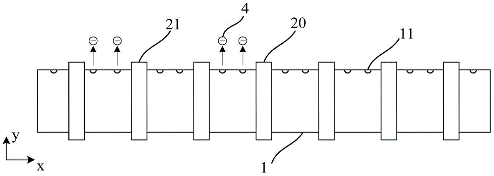
[0046] refer to figure 1 and figure 2 , the electron supply system described in this embodiment includes a cavity 1, which is filled with gas, and the side wall of the cavity 1 is provided with extraction units distributed along the length direction (x direction) of the cavity, In this embodiment, the extraction unit is a plurality of through holes 11 arranged along the x direction, and a cathode 3 is arranged in the cavity 1, and the cathode 3 is used to emit electrons.

[0047] The electron supply system also includes a plurality of magnetic devices 20, 21 surrounding the cavity (the magnetic device corresponding to the cathode position is indicated by 20, and the other magnetic devices located on both sides of the magnetic device 20 are indicated by 21), a plurality of The magnetic devices are arranged at intervals along the length direction of the cavity, and the superimposed magnetic field of these magnetic devices makes: in the cavity, electrons can be distributed in t...

Embodiment 2

[0055] The basic principle of embodiment 2 is the same as that of embodiment 1, the only difference is:

[0056] In this embodiment, the lead-out unit is a strip-shaped slot hole, the length direction of the slot hole is consistent with the length direction of the cavity, and the magnetic device is an electromagnet, and the current on the coil of the electromagnet is adjustable. .

[0057] Refer to Example 1 for all the other unmentioned parts.

Embodiment 3

[0059] The basic principle of embodiment 3 is the same as embodiment 1, the only difference is:

[0060] In this embodiment, the number of the cathode is one. In the length direction of the cavity, the cathode is placed in the middle of the cavity, and the installation positions of the magnetic devices are axisymmetrically distributed, and the axis of symmetry is perpendicular to the cavity. in the lengthwise direction and through the cathode,

[0061] Wherein, in the length direction of the cavity, from the cathode to the direction away from the cathode, the magnetic field strength of the magnetic device decreases successively, and some electrons move from the position with strong magnetic field strength to the position with weak magnetic field along the length direction of the cavity. positional movement,

[0062] And the magnetic field formed by two adjacent magnetic devices enables another part of electrons to be confined in the space between the two adjacent magnetic dev...


PUM


Abstract

The invention discloses an electron supply system, which comprises a cavity. The side wall of the cavity is provided with leading-out units distributed along the length direction of the cavity; and the cavity is provided with at least one cathode for emitting electrons. The electron supply system also comprises multiple magnetic devices around the cavity, the multiple magnetic devices are arranged along the length direction of the cavity at intervals, and due to the overlapped magnetic field of the magnetic devices, in the cavity, the electrons are distributed in the length direction of the cavity, and the leading-out units are used for leading one part of electrons out to form a ribbon electron group. The one-stage or multi-stage magnetic field is adopted to limit movement of the electrons in the not ideal direction, the majority of electrons can be distributed along the width direction of the ribbon ion beam, neutralization of the large-sized ion beam can be realized, impact loss of the electrons before certain distribution is formed can be avoided, and the electrons for neutralization can always have enough quantity.

Description

technical field [0001] The invention relates to an electron supply system, in particular to an electron supply system capable of extracting large-sized electron clusters generally in the form of bands. Background technique [0002] In ion implantation, due to the influence of the space charge effect, the uniformity of the large-sized ribbon ion beam will be lost, thereby affecting the subsequent implantation process. In order to eliminate the influence of the space charge effect as much as possible, electron neutralization is introduced in the industry, that is, electrons are used to neutralize the ion beam during the transmission process, so as to alleviate the influence of the space charge effect on the shape of the ion beam. [0003] In the existing neutralization system, a PEFG (plasmaelectronfloodgun, plasma electron flow gun) is used to provide electrons to the ion beam to neutralize the positive charges in the ion beam. However, as the size of the processed wafer bec...

Claims


Application Information

Patent Timeline
Patent Type & Authority Applications(China)
IPC IPC(8): H01J37/317H01J37/30
Inventor 陈炯洪俊华张劲
Owner 北京凯世通半导体有限公司
Learn More