
Torque transmission shaft with yoke for universal joint and manufacturing method therefor

A technology for universal joints and manufacturing methods, which is applied to steering control, shafts, and applications installed on vehicles, and can solve problems such as the difficulty in reducing the weight of the intermediate shaft 5 and increasing manufacturing costs, so as to ensure strength and suppress manufacturing costs Effect

Active Publication Date: 2016-04-06
NSK LTD
View PDF11 Cites 6 Cited by
  • Summary
  • Abstract
  • Description
  • Claims
  • Application Information

AI Technical Summary

Problems solved by technology

However, labor and time are required for cutting such as turning on the portion near the other end in the axial direction of the first blank rod portion 13, and not only the manufacturing cost of the torque transmission shaft 17 with the yoke for a universal joint increases, but also the male Groove bottom diameter d of spline part 11 11 If it is larger than necessary, it is difficult to reduce the weight of the entire intermediate shaft 5 including the torque transmission shaft 17 with the yoke for universal joints.

Method used


Image

  • Torque transmission shaft with yoke for universal joint and manufacturing method therefor
  • Torque transmission shaft with yoke for universal joint and manufacturing method therefor
  • Torque transmission shaft with yoke for universal joint and manufacturing method therefor

Examples


no. 1 Embodiment approach

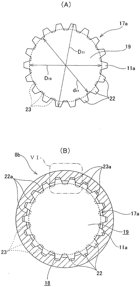
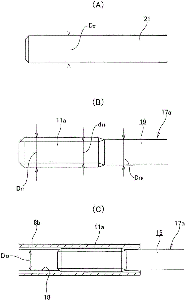
[0077] use Figure 1-7 The first embodiment of the present invention will be described. figure 1 The completed state of the torque transmission shaft 17a with the yoke for universal joints of this embodiment is shown. A torque transmission shaft 17a with a yoke for a universal joint is at one axial end ( figure 1 A male spline portion 11a is provided on the outer peripheral surface of the left end portion of the rod portion 19, and the other axial end portion of the rod portion 19 ( figure 1 The right end portion of the fork yoke 9) is fixedly provided with a base end portion of a yoke 9 having a cross shaft 10 for constituting a cross shaft universal joint 4a (refer to Figure 12 A pair of arm portions 20, 20 pivotally supported by two end portions on radially opposite sides among the four end portions provided on ). In particular, in the case of the torque transmission shaft 17a with the yoke for a universal joint according to this embodiment, the groove bottom diamete...

no. 2 Embodiment approach

[0089] use Figure 8-9 A second embodiment of the present invention will be described. Figure 8 A state in which the torque transmission shaft 17b with the yoke for universal joints of this embodiment is combined with the torque transmission shaft 8b to form the intermediate shaft 5 is shown. Moreover, the torque transmission shaft 17b with the yoke for universal joints of this embodiment is characterized by the structure of the coating layer 24c made of a low-friction material provided on the surface of the male spline part 11a. The structure and manufacturing method of the other parts are the same as those of the torque transmission shaft 17a with a yoke for a universal joint in the first embodiment described above, so the following description will focus on the structure of the coating layer 24c.

[0090] In the case of the present embodiment, the covering layer 24c is formed over the entire length and the entire circumference of the male spline portion 11a. In the cover...


PUM


Abstract

The invention relates to a torque transmission shaft with a yoke for a universal joint and a manufacturing method therefor. By plastic working of one axial end of a rod-shaped element (21), which has an outer diameter (D21) that coincides with the outer diameter (D19) of the completed rod section (19) and on the other axial end of which the base end of a forked yoke (9) is fixed, to change the shape of the outer circumferential surface of the one axial end in the radial direction, a male spline section (11a), wherein the root circle diameter (d11) is smaller than the outer diameter of the rod section (19) and the addendum circle diameter (D11) is greater than the outer diameter of the rod section (19), is formed on the outer circumferential surface of the one axial end.

Description

technical field [0001] The present invention relates to, for example, a torque transmission shaft with a yoke for a universal joint that constitutes a steering device for an automobile and constitutes an intermediate shaft for transmitting rotation of the steering shaft to an input shaft of a steering gear unit, and a manufacturing method thereof. Background technique [0002] As a steering device for automobiles, conventionally, such as Figure 11 steering gear as shown. This steering device has a configuration capable of imparting a desired steering angle to left and right steering wheels (not shown) by converting the rotational motion of the steering wheel 1 operated by the driver into linear motion by the steering gear unit 2 . In order to realize such a configuration, specifically, the steering wheel 1 is fixed to the rear end portion of the steering shaft 3 . At the same time, the front end portion of the steering shaft 3 is connected to the base end portion of the in...

Claims


Application Information

Patent Timeline
Patent Type & Authority Applications(China)
IPC IPC(8): F16D3/06F16C3/02F16D1/02F16D1/06
CPCF16D1/0858F16D3/387F16C3/03F16D2001/103F16D2003/22326B62D1/16B62D1/20F16C2326/24Y10T403/7035F16D1/101B29C43/16B29C43/18B29L2031/75
Inventor 黑川祥史
Owner NSK LTD
Learn More