Method for conducting leaching and flotation on ores in same leaching and flotation cells

A flotation tank and leaching technology, which is applied in the field of ore leaching and flotation in the same tank, can solve the problems of large equipment investment, high consumption of equipment and spare parts, and increase of post personnel, so as to improve the concentrate quality index and good technical and economic indicators , Improve the effect of recovery rate index

Active Publication Date: 2016-04-13
罗光臣
View PDF2 Cites 5 Cited by
  • Summary
  • Abstract
  • Description
  • Claims
  • Application Information

AI Technical Summary

Problems solved by technology
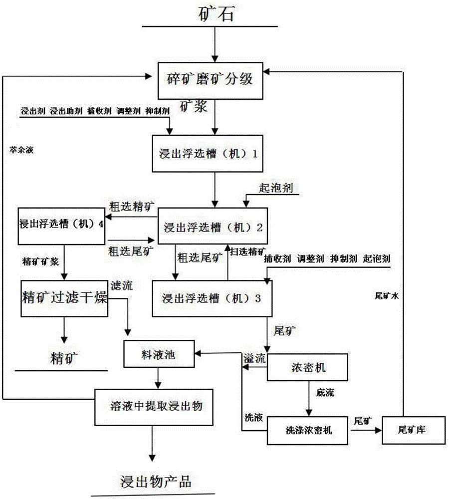
[0004] The existing problems of the ore slurry first leaching and then flotation process and the first flotation and then leaching process are: 1. Long process and large investment
Long process, large equipment investment, large civil construction investment
2. High energy consumption, high consumption of equipment and spare parts, increase of post personnel, high production cost
3. Large amount of wastewater treatment

Method used


Image

  • Method for conducting leaching and flotation on ores in same leaching and flotation cells
  • Method for conducting leaching and flotation on ores in same leaching and flotation cells
  • Method for conducting leaching and flotation on ores in same leaching and flotation cells

Examples


Embodiment 1

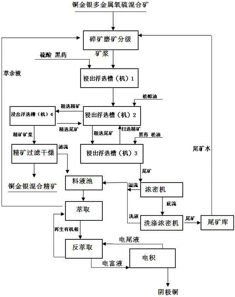
[0047] Such as figure 2 Shown, the method that copper-gold-silver multi-metal oxysulfur mixed ore leaching and flotation are carried out in the same tank in the leaching flotation cell (machine):

[0048] 1. Reaction mechanism in leaching flotation tank (machine)

[0049] 1.1 Leaching chemical reaction mechanism

[0050] CuCO 3 ·Cu(OH) 2 (Malachite)+H 2 SO 4 →2CuSO 4 +3H 2 O+CO 2

[0051] Cu 2 O(Cuprite)+H 2 SO 4 →CuSO 4 +Cu+H 2 o

[0052] Cu 3 (CO 3 ) 2 (OH) 2 (Azurite)+H 2 SO 4 →CuSO 4 +H 2 O+CO 2

[0053] (Cu, Al) 2 h 2 Si 2 o 5 (OH) 4 ·nH 2 O(chrysocolla)+H 2 SO 4 →CuSO 4 +Al 2 SO 4 +SiO2 2 .nH 2 O+H 2 O.

[0054] CaO+H 2 SO 4 →CaSO 4 +H 2 o

[0055] MgO+H 2 SO 4 → MgSO 4 +H 2 o

[0056] AL 2 o 3 +H 2 SO 4 →ALSO 4 +H 2 o

[0057] 1.2 Physicochemical reaction mechanism of flotation

[0058] CuS+ROCSS-Na→ROCSS-CuS+Na +

[0059] Cu2S+ROCSS-Na→ROCSS-Cu2S+Na +

[0060] Cu+ROCSS-Na→ROCSS-Cu+Na +

[0061] CuFeS 2 +ROC...

Embodiment 2

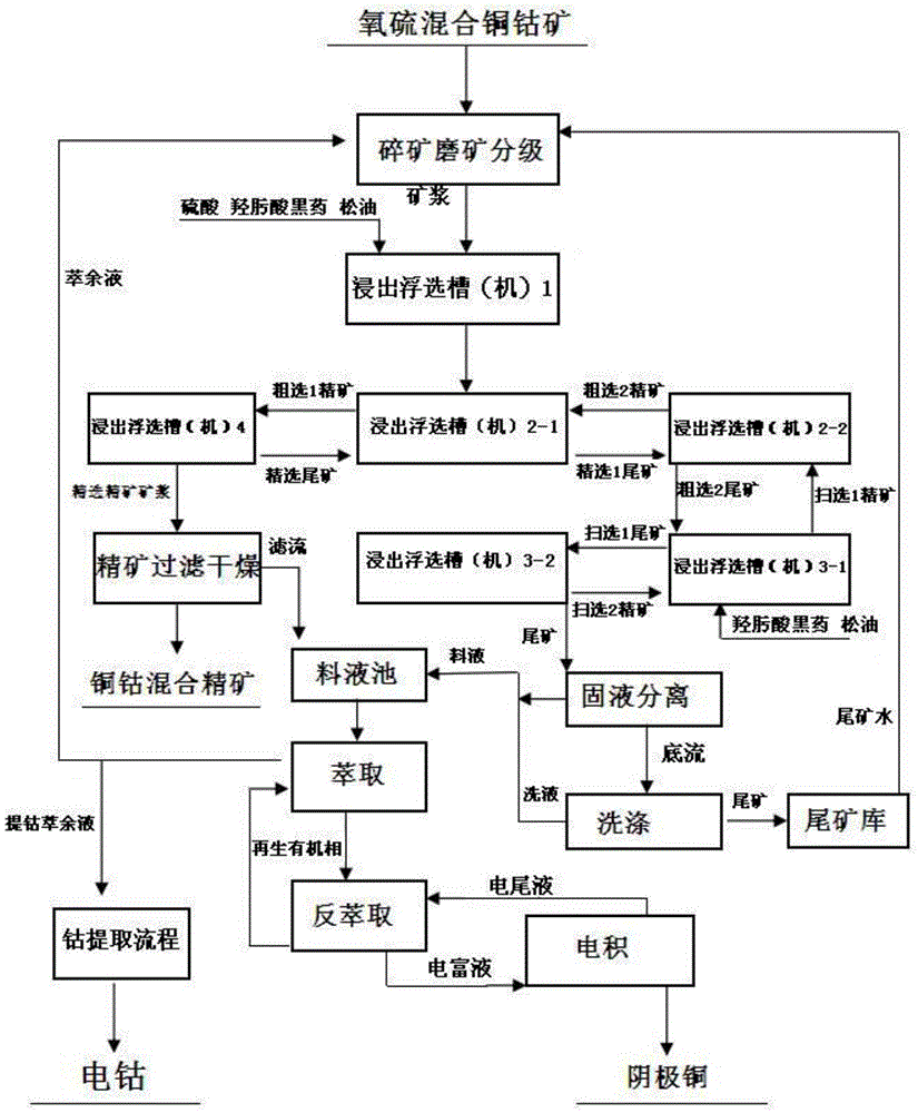
[0082] image 3 Shown is the process flow of stirring leaching and flotation of copper-cobalt-oxygen-sulfur mixed ore carried out in the same tank in the leaching flotation tank (machine).

[0083] 1. Reaction mechanism in leaching flotation tank (machine)

[0084] 1.1 Leaching chemical reaction mechanism

[0085] CuCO 3 ·Cu(OH) 2 (Malachite)+H 2 SO 4 →2CuSO 4 +3H 2 O+CO 2

[0086] Cu 2 O(Cuprite)+H 2 SO 4 →CuSO 4 +Cu+H 2 o

[0087] Cu 3 (CO 3 ) 2 (OH) 2 (Azurite)+H 2 SO 4 →CuSO 4 +H 2 O+CO 2

[0088] (Cu, Al) 2 h 2 Si 2 o 5 (OH) 4 ·nH 2 O(chrysocolla)+H 2 SO 4 →CuSO 4 +Al 2 SO 4 +SiO2 2 .nH 2 O+H 2 O.

[0089] CoO+H 2 SO 4 →CoSO 4 +H 2 o

[0090] CaO+H 2 SO 4 →CaSO 4 +H 2 o

[0091] MgO+H 2 SO 4 → MgSO 4 +H 2 o

[0092] AL 2 o 3 +H 2 SO 4 →ALSO 4 +H 2 o

[0093] 1.2 Physicochemical reaction mechanism of flotation

[0094] CuS+ROCSS-Na→ROCSS-CuS+Na +

[0095] Cu 2 S+ROCSS-Na→ROCSS-Cu 2 S+Na +

[0096] Cu+ROCSS...


PUM


Abstract

The invention provides a method for conducting leaching and flotation on ores in the same leaching and flotation cells. The method is characterized in that the ores are leached and floated in the same leaching and flotation cells; and the leaching and flotation cells are divided into two or more sections according to the chemical mixing, roughing, scavenging and fine selecting functions required by the flotation procedure in the procedure, and each section is provided with at least one leaching and flotation cell. The method has the beneficial effects that leaching and flotation are performed in the same cells, so that the leaching process, the flotation process, a leaching system, a flotation system, a leaching agent, a floating agent and leaching liquid are coordinated, and the recovery rate index and the concentrate quality index are increased. The leaching process and the flotation process are better combined. The procedure of the method is shorter than the procedure in which the ores are leached firstly and then floated or floated firstly and then leached in the prior art, equipment investment is saved, energy consumption is low, used labor is small, and production cost is low.

Description

technical field [0001] The invention belongs to the field of combination of ore hydrometallurgy and mineral processing technology. It belongs to the new technology field of ore leaching flotation in the same tank. Background technique [0002] The existing ore leaching process has few kinds of metals in polymetallic ore that can be leached and extracted under the same leaching system, and the recovery rate for leaching of oxygen-sulfur mixed ore and leaching of sulfide ore is low. Flotation has a high recovery rate for sulfide ore in minerals, and a low recovery rate for oxidized ore in minerals. For polymetallic symbiotic ores and oxygen-sulfur mixed ores, only leaching or flotation is used, and the comprehensive recycling level of resources is not high. For example, for copper-silver-gold symbiotic oxygen-sulfur mixed ore, sulfuric acid leaching can only recover copper, but gold and silver cannot be leached and recovered; for copper-silver-gold symbiotic oxygen-sulfur mi...

Claims


Application Information

Patent Timeline
Patent Type & Authority Applications(China)
IPC IPC(8): C22B3/04B03D1/018
CPCB03D1/018C22B3/04
Inventor 罗光臣向文之
Owner 罗光臣
Why Eureka
Try Eureka