
Manufacturing method of touch display panel

A technology for touch display panels and manufacturing methods, applied in the input/output process of data processing, instruments, calculations, etc., which can solve the problems of panel rework and easily scratched ITO layers, etc.

Active Publication Date: 2018-12-18
KUSN INFOVISION OPTOELECTRONICS
View PDF6 Cites 0 Cited by
  • Summary
  • Abstract
  • Description
  • Claims
  • Application Information

AI Technical Summary

Problems solved by technology

[0005] Since the touch sensing layer—the ITO layer is prefabricated on one side of the CF substrate, and then CF is fabricated on the other side of the CF substrate, when performing CF fabrication, the CF substrate must be turned over so that the side where the ITO layer is located faces The ITO layer is in direct contact with the machine, and it is easy to scratch the ITO layer, which will cause the panel to be reworked or scrapped

Method used


Image

  • Manufacturing method of touch display panel
  • Manufacturing method of touch display panel
  • Manufacturing method of touch display panel

Examples


Embodiment Construction

[0017] In order to make the purpose, technical solution and advantages of the present invention clearer, the embodiments of the present invention will be further described in detail below in conjunction with the accompanying drawings.

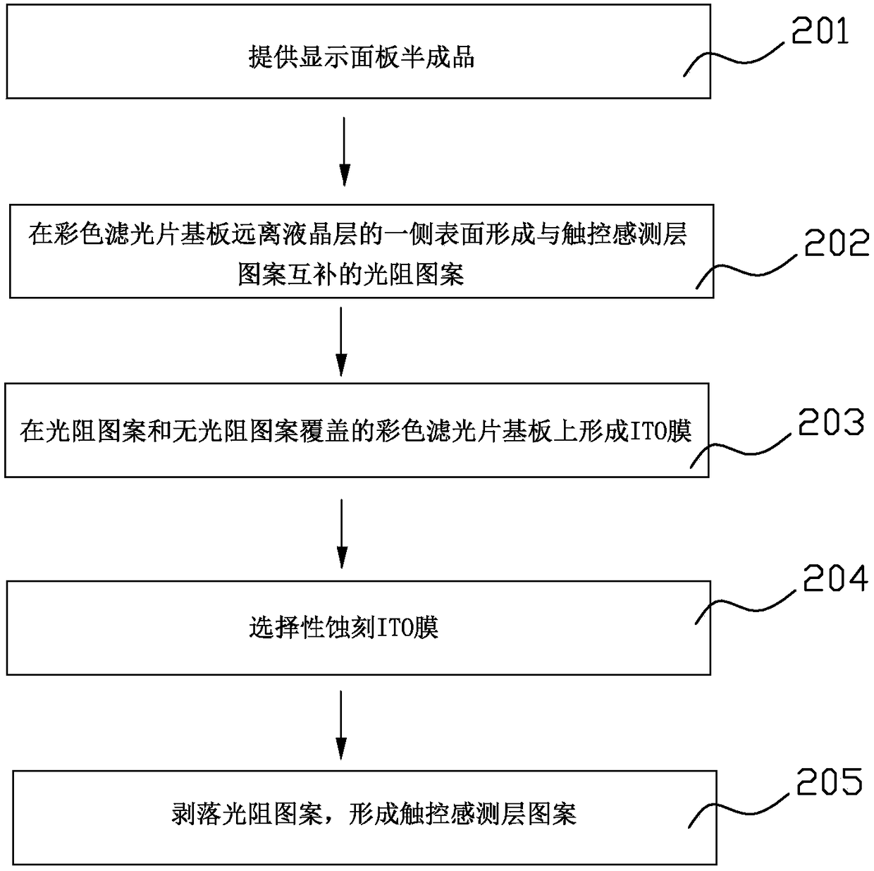
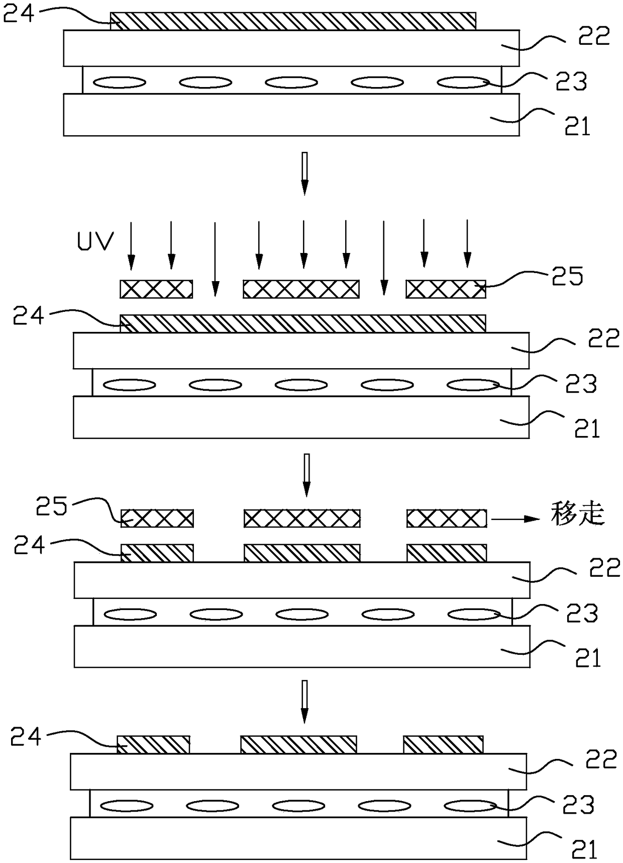
[0018] figure 1 It is a flowchart of a manufacturing method of a touch display panel in an embodiment of the present invention, Figure 2A to Figure 2E It is a schematic cross-sectional structure diagram of the touch display panel in each step in one embodiment of the present invention. Such as figure 1 As shown, a method for manufacturing a touch display panel in an embodiment of the present invention includes the following steps:

[0019] S201: Provide display panel semi-finished products;

[0020] S202: Forming a photoresist pattern complementary to the pattern of the touch sensing layer on the surface of the color filter substrate away from the liquid crystal layer;

[0021] S203: forming an ITO film on the photoresist pattern and the c...


PUM

PropertyMeasurementUnit
thicknessaaaaaaaaaa

Abstract

The invention provides a manufacturing method of a touch control display panel. The method includes the steps that a display panel semi-finished product is provided, the display panel semi-finished product comprises an array substrate, a color filter substrate and a liquid crystal layer, the liquid crystal layer is located between the array substrate and the color filter substrate, and according to the display panel semi-finished product, assembling of the array substrate, the color filter substrate and the liquid crystal layer is completed; a photoresistance pattern complementary to a touch control sensing layer pattern is formed on the surface of the side, away from the liquid crystal layer, of the color filter substrate; an ITO membrane is formed on the photoresistance pattern and the color filter substrate which is not covered with the photoresistance pattern; the ITO membrane is etched selectively, the ITO membrane above the photoresistance pattern is etched and removed, the photoresistance pattern is exposed, and the ITO membrane above the color filter substrate which is not covered with the photoresistance pattern is maintained; the photoresistance pattern is stripped off, and the touch control sensing layer pattern is formed.

Description

technical field [0001] The present invention relates to the technical field of touch display, in particular to a method for manufacturing a touch display panel. Background technique [0002] With the development of the information age and the acceleration of the pace of life, touch technology has gradually replaced the traditional mouse and keyboard due to its humanized design and simple and fast input, and is widely used in various electronic products. Among them, the capacitive touch screen is widely used due to its advantages of fast response, high sensitivity, good reliability and high durability. The capacitive touch screen mainly includes a protective glass (Cover Lens) and a touch sensing layer (Touch Sensor). Its sensing principle is to apply a voltage to the four corners of the screen sensing area and form a fixed electric field. The capacitance change between the transparent electrode and the transparent electrode can cause the electric field to induce a current, ...

Claims


Application Information

Patent Timeline
Patent Type & Authority Patents(China)
IPC IPC(8): G02F1/1333G06F3/041
CPCG02F1/13338G06F3/0412
Inventor 何佳新
Owner KUSN INFOVISION OPTOELECTRONICS
Learn More