Cooling module and cooling system for vehicle

一种冷却模块、车辆的技术,应用在动力装置的冷却结合的布置、车辆储能、车辆部件等方向,能够解决第二散热器性能不良影响、难以保证第二散热器稳定性能等问题,达到减小负荷的效果

Active Publication Date: 2016-04-13
HANON SYST
View PDF4 Cites 26 Cited by
  • Summary
  • Abstract
  • Description
  • Claims
  • Application Information

AI Technical Summary

Problems solved by technology

However, the heated air passing through the condenser (30) passes through the second radiator (21), thereby adversely affecting the performance of the second radiator (21)
[0016] Further, according to the load of the condenser (30), the air supplied to the second radiator (21) has a large temperature difference, so that it is difficult to guarantee the stable performance of the second radiator (21)

Method used


Image

  • Cooling module and cooling system for vehicle
  • Cooling module and cooling system for vehicle
  • Cooling module and cooling system for vehicle

Examples


Embodiment Construction

[0086] Hereinafter, a description will be given in detail of a cooling module (1000) and a cooling system (2000) for a vehicle according to the present invention with reference to the accompanying drawings.

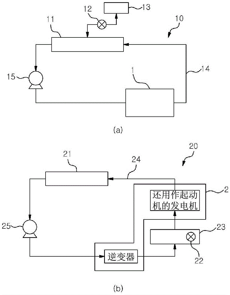
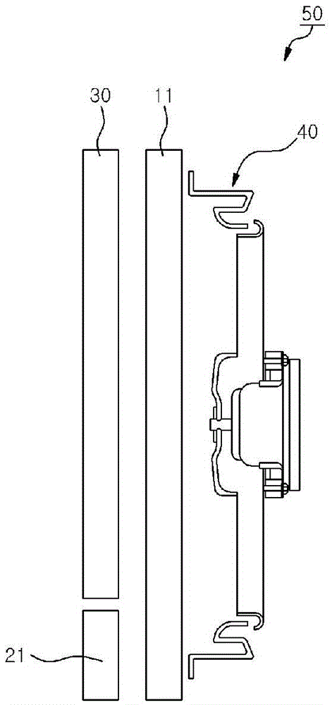
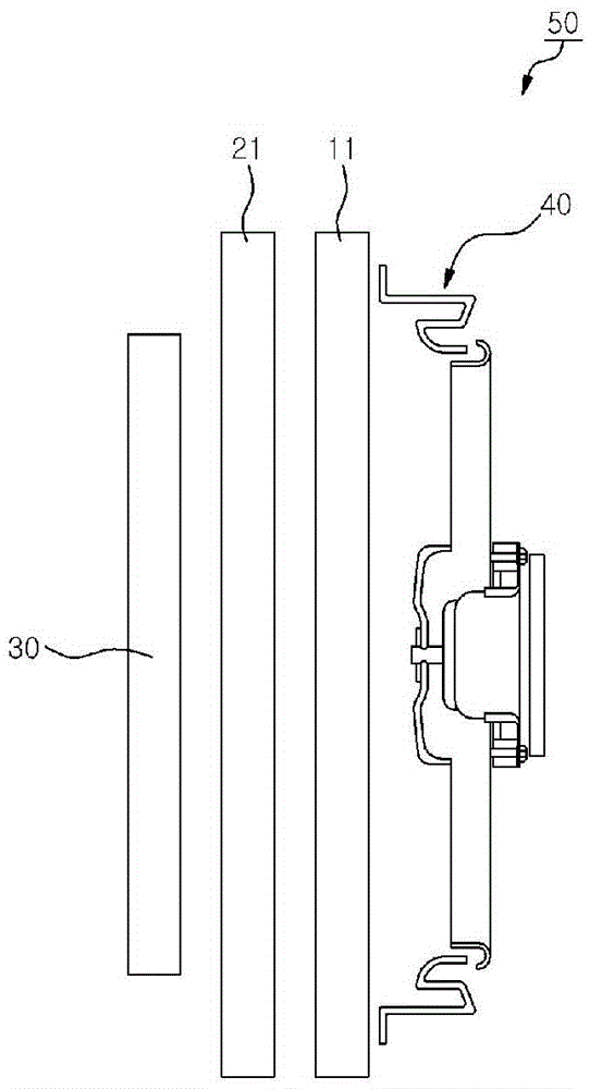
[0087] Figure 4 to Figure 7 is a perspective view, an exploded perspective view, a longitudinal section view and a top plan view showing a cooling module (1000) according to the present invention, Figure 8 and 9 is a sectional view and a perspective view showing the second condenser (400) of the cooling module (1000) according to the present invention, Figure 10 and Figure 11 is a front view showing cooling water flowing inside the second radiator (200) of the cooling module (1000) according to the present invention, Figure 12 is a perspective view showing refrigerant flow in a cooling module (1000) according to the present invention, Figure 13 is a perspective view showing a cooling system (2000) for a vehicle according to the present invention.

[0088] Accor...


PUM


Abstract

A cooling module (1000) of the present invention comprises: a first radiator (100) for cooling an engine; a second radiator (200) which is located at the front side of the first radiator (100) in an air flowing direction, and which cools electric components; a first condenser (300) which is located at the front side of the second radiator (200) in the air flowing direction, and which condenses a refrigerant by exchanging heat with outside air; and a second condenser (400) which is provided inside the second radiator (200), and which condenses a refrigerant by exchanging heat with an electric component coolant. Thus, the cooling module (1000) of the present invention enables a high-temperature and high-pressure refrigerant to pass through the air-cooled first condenser (300) after passing the water-cooled second condenser (400) so as to increase cooling efficiency of the refrigerant, thereby improving the efficiency of a cooling system (2000) for a vehicle.

Description

technical field [0001] The present invention relates to a cooling module and a cooling system for a vehicle, and more particularly, to such a cooling module and a cooling system for a vehicle, which include a first radiator, a second radiator, a first condenser and A second condenser located inside the second radiator, thereby enhancing refrigerant condensation performance to provide improved cooling efficiency and reduced compressor load. Background technique [0002] Generally, in a vehicle mounted with an internal combustion engine, heat generated during operation of the engine is transferred to the cylinder head, piston, and valves, and accordingly, if the temperature of these parts rises excessively, thermal expansion or degradation occurs, Thereby reducing the strength of components, reducing the life of the engine, resulting in a bad combustion state causing knocking or pre-ignition, and reducing the output of the engine. [0003] Further, in the case of incomplete c...

Claims


Application Information

Patent Timeline
Patent Type & Authority Applications(China)
IPC IPC(8): B60K11/06F28F9/02F28F1/10F25B39/04F25B43/02B60H1/32
CPCF25B6/04F25B2339/047B60H1/3227F28F9/0234F28D1/0435B60K2001/003B60K2001/005B60K2001/006F25B39/04F28D1/05391B60K11/04B60K11/06F28F9/02B60H1/32Y02T10/70F25B39/00F28D1/05325F28F1/10
Inventor 崔隽瑛申贤根安容男
Owner HANON SYST
Why Eureka
Try Eureka