an electric dust collector

A technology of electrostatic precipitator and electric field, which is applied in the direction of external electrostatic separator, electrode cleaning, electrostatic separation, etc., can solve the problems of poor matching of plate horizontal electrostatic precipitator, influence of dust removal effect of electrostatic precipitator, and increase of economic cost, etc., to achieve Avoid secondary dust, improve the effect of dust removal, and improve the effect of dust removal efficiency

Active Publication Date: 2017-05-24
FUJIAN LONGKING DSDN ENGINEERING CO LTD
View PDF9 Cites 0 Cited by
  • Summary
  • Abstract
  • Description
  • Claims
  • Application Information

AI Technical Summary

Problems solved by technology

[0005] However, when the flue gas passes through the above-mentioned plate horizontal electrostatic precipitator, it enters and exits horizontally, and the dust vibrated from the pole line and the pole plate is easily entrained by the horizontal airflow during the vertical falling process under the action of its own weight, causing secondary dust and affecting The dust removal effect of the electrostatic precipitator is improved; at the same time, for some industrial kilns or process devices with a higher central position of the flue gas outlet, the matching with the plate horizontal electrostatic precipitator is poor, and additional flue and steel brackets need to be added, which is easy Larger floor space and increased economic costs

Method used


Image

  • an electric dust collector
  • an electric dust collector
  • an electric dust collector

Examples


Embodiment Construction

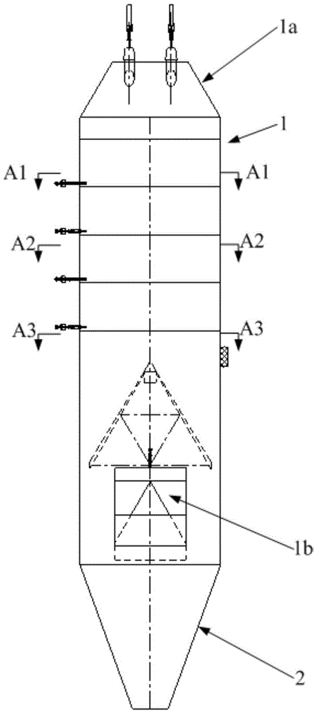
[0057] The embodiment of the present invention provides an electrostatic precipitator, which can improve the dust removal effect of the electrostatic precipitator, reduce the occupied area, ensure the compatibility with other process devices with a higher central position of the flue gas outlet, and further reduce the economic cost.

[0058] In order to make the purpose, technical solutions and advantages of the embodiments of the present invention clearer, the technical solutions in the embodiments of the present invention will be clearly and completely described below in conjunction with the drawings in the embodiments of the present invention. Obviously, the described embodiments It is a part of embodiments of the present invention, but not all embodiments. Based on the embodiments of the present invention, all other embodiments obtained by persons of ordinary skill in the art without making creative efforts belong to the protection scope of the present invention.

[0059] ...


PUM


Abstract

The invention provides an electric dust remover. The electric dust remover comprises a barrel-shaped shell, a plurality of tubular precipitating electrodes, a plurality of corona electrode wires and a rapping device, wherein the barrel-shaped shell is arranged along the vertical direction; a flue gas inlet is formed in the top of the barrel-shaped shell and a flue gas outlet is formed in the bottom of the barrel-shaped shell; an electric field region is arranged on one side, close to the flue gas inlet, in the barrel-shaped shell; flue gas passes through the tubular precipitating electrodes and the tubular precipitating electrodes are arranged in the electric field region along the vertical direction; the corona electrode wires are arranged on the axes of the tubular precipitating electrodes, are electrically connected with a high-voltage power supply, and correspond to the tubular precipitating electrodes one by one; and the rapping device is used for removing dust on the tubular precipitating electrodes and the corona electrode wires and is arranged outside the barrel-shaped shell. According to the electric dust remover, the flue gas enters from the top and flows out from the bottom, so that self-settling of the high-concentration dust is facilitated; meanwhile, the flow direction of the flue gas and the falling direction of rapped falling dust are consistent so that secondary dust raising is avoided and the dust removing effect of the electric dust remover can be improved; and meanwhile, the occupied area is reduced, and the matching of the dust remover with other process devices with relatively high flue gas outlet center positions also can be guaranteed, so that the economic cost is reduced.

Description

technical field [0001] The invention relates to the technical field of flue gas dust removal, and more specifically, to an electric dust collector. Background technique [0002] In the glass kiln, non-ferrous smelting and other industrial fields, the temperature of the dusty gas coming out of the kiln is as high as 350°C or even higher. Due to the characteristics of the fuel, the dust in the flue gas is also highly viscous and easy to absorb moisture. Therefore, in order to ensure the normal operation of subsequent process equipment, it is necessary to remove dust at high temperature. [0003] At present, to achieve flue gas dust removal under high temperature and high pressure conditions, the main technologies used are filter dust removal technology and electrostatic dust removal technology. Electrostatic dust removal technology is to use the strong electric field generated by the DC high voltage power supply to ionize the gas, generate corona discharge, and then charge th...

Claims


Application Information

Patent Timeline
Patent Type & Authority Patents(China)
IPC IPC(8): B03C3/06B03C3/76B03C3/34B03C3/36B03C3/88B03C3/86
CPCB03C3/06B03C3/34B03C3/363B03C3/76B03C3/86B03C3/88
Inventor 张原陈耀亮赖毅强林春源王建春
Owner FUJIAN LONGKING DSDN ENGINEERING CO LTD
Why Eureka
Try Eureka