
Automatic worm residual tooth removing device and residual tooth removing method thereof

A technology for worms and residual teeth, which is applied in the field of automatic worm gear removal devices, can solve the problems of high labor intensity, inability to grind residual teeth, and low processing efficiency, so as to reduce labor intensity, reduce product scrap rate, and improve processing efficiency effect

Active Publication Date: 2016-04-20
ZHEJIANG ESSOR PRECISION MACHINERY
View PDF10 Cites 4 Cited by
  • Summary
  • Abstract
  • Description
  • Claims
  • Application Information

AI Technical Summary

Problems solved by technology

Disadvantages: This kind of worm residual burr removal machine can only remove residual burrs that affect the meshing of worm gears, but cannot smooth the sharp edges on residual teeth that are easy to cut hands. Now, manual polishing machine is used for grinding residual teeth The method is not only labor-intensive, but also has a high scrap rate and low processing efficiency.

Method used


Image

  • Automatic worm residual tooth removing device and residual tooth removing method thereof
  • Automatic worm residual tooth removing device and residual tooth removing method thereof

Examples


Embodiment 1

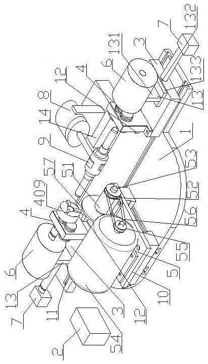
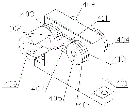
[0010] Embodiment 1: with reference to attached figure 1 and figure 2 . An automatic worm gear removal device, comprising a base 1 and a controller 2, two moving seats 3 are provided opposite to each other on the upper end of the base 1, and a group of variable trajectory rotating clamp assemblies 4 are respectively arranged on the two moving seats 3, The base 1 between the two moving seats 3 is provided with a track 11, the track 11 is convenient for the relative movement of the two moving seats 2, so that the worm can be clamped between the two tops 409 of the two groups of variable track rotating clamp assemblies 4, the track 11 There are two groups of shock-absorbing stoppers 12 on the top, which ensure that the two groups of variable-trajectory rotary clamp assemblies 4 driven by the two cylinders 7 can clamp the worm at a predetermined position, and the two groups of variable-trajectory rotation The clip assembly 4 is driven to rotate synchronously by two stepper moto...

Embodiment 2

[0011]Embodiment 2: On the basis of Embodiment 1, a method for removing residual teeth of an automatic worm screw removal device, firstly place the worm on the manipulator 9 and adjust the worm so that the outer contour of the residual teeth to be polished in the worm and the cam 403 The outer contours are aligned; then the grinding wheel 57 grinds the remaining teeth on one side of the worm. Under the control of the controller 2, firstly, when the manipulator 9 clamps the middle part of the worm, the two cylinders 7 push the two moving seats 3 so that the two ends of the worm are located at the two ends. Among the two pneumatic chucks 409, the second two pneumatic chucks 409 clamp the two ends of the worm while the manipulator 9 releases the worm, and then two stepping motors 6 synchronously drive the two pneumatic chucks 409 and are clamped between the two pneumatic chucks 409. While the worm rotates, the slider of the servo slide 10 drives the grinding wheel assembly 5 to mo...


PUM


Abstract

The invention relates to an automatic worm residual tooth removing device capable of smoothening residual teeth on the two sides of a worm at a time and a residual tooth removing method thereof. The automatic worm residual tooth removing device is characterized in that two movable seats are oppositely arranged on the upper end surface of a base; a variable track rotating clamp assembly is arranged on each of the two movable seats; the two variable track rotating clamp assemblies are synchronously driven to rotate by two stepping motors respectively; two cylinders are arranged on the upper end surface of the base, and are respectively positioned on the two sides of the two movable seats; piston ends of the two cylinders are fixedly connected with the outer side surfaces of the two movable seats respectively; a rotary table mounting seat is arranged on one side of the base; a rotary table is horizontally mounted on the rotary table mounting seat; a mechanical hand is horizontally arranged on the table surface of the rotary table; a clamping part of the mechanical hand is positioned right between the two movable seats; a servo sliding table is arranged on the upper end surface of the base; and a grinding wheel assembly is arranged on a sliding block of the servo sliding table. The automatic worm residual tooth removing device has the advantages that residual sharp edge parts on the worm can be quickly and uniformly smoothened, so that the processing efficiency is improved, and the rejection rate of a product is decreased.

Description

technical field [0001] The invention relates to an automatic worm gear removing device and a method for removing residual teeth capable of grinding residual teeth on both sides of a worm at one time, and belongs to the field of worm processing equipment manufacturing. Background technique [0002] CN203197401U, the name "a kind of deburring machine for residual worm teeth", includes a worm processing machine tool, polishing blocks are respectively installed on the guide rails on both sides of the worm processing machine tool, and the polishing wheels of the polishing blocks contact the tooth surfaces at both ends of the worm. The base of the polishing block is buckled on the guide rail and has a buckling and moving fit. Disadvantages: This kind of worm residual burr removal machine can only remove residual burrs that affect the meshing of worm gears, but cannot smooth the sharp edges on residual teeth that are easy to cut hands. Now, manual polishing machine is used for grin...

Claims


Application Information

Patent Timeline
Patent Type & Authority Applications(China)
IPC IPC(8): B23F13/00B23F19/00
CPCB23F13/00B23F19/00
Inventor 陈金山林秀薰
Owner ZHEJIANG ESSOR PRECISION MACHINERY
Learn More