A control method and control device for internal holes in a weld during laser welding

An internal hole, laser welding technology, used in laser welding equipment, welding equipment, manufacturing tools, etc., can solve the problems of difficult implementation, narrow process window, concave weld seam, etc., and achieve simple and easy implementation, low cost and convenient effect. Effect

Active Publication Date: 2018-01-02
武汉翔明激光科技有限公司
View PDF1 Cites 0 Cited by
  • Summary
  • Abstract
  • Description
  • Claims
  • Application Information

AI Technical Summary

Problems solved by technology

There are also people who reduce the number and size of holes in the weld by controlling the gap and the amount of misalignment during welding. Other methods such as pre-treatment of materials and the use of special welding wires for laser hybrid welding can reduce the number of holes in laser welding to a certain extent. Holes in the process, but both increase the complexity of the process and operation, and some methods are difficult to implement in production practice
[0005] The Chinese patent specification whose patent application number is 201210390068.6 discloses a control method and a control device for holes inside the weld during laser welding. It is easy to absorb part of the liquid in the molten pool, destroying the stability of the molten pool, the process window is narrow, and defects such as weld sinking are easy to occur

Method used


Image

  • A control method and control device for internal holes in a weld during laser welding
  • A control method and control device for internal holes in a weld during laser welding
  • A control method and control device for internal holes in a weld during laser welding

Examples


Embodiment 1

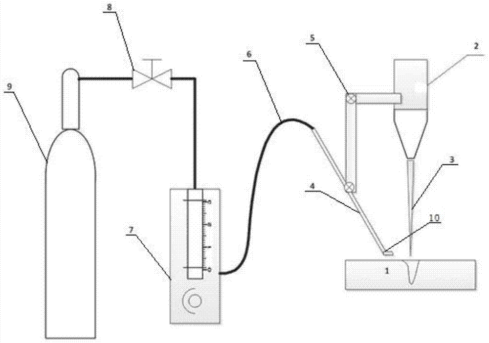
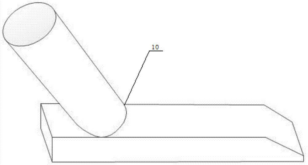
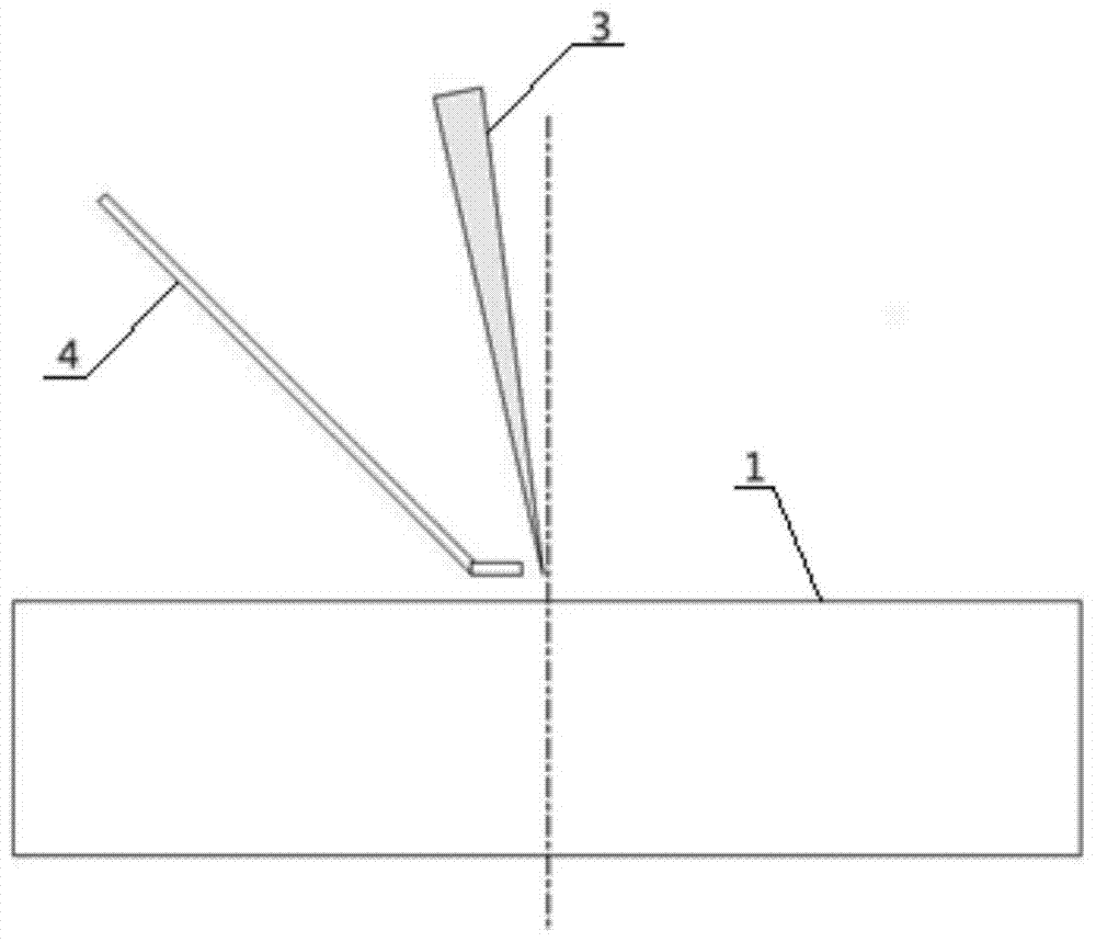
[0025] When the laser head 2 of the laser device emits laser light 3 to carry out deep penetration welding on the workpiece 1, the air blowing device is used to blow out the air flow above the molten pool 12 to form a local negative pressure above the molten pool 12 and the keyhole 11, thereby The steam in the keyhole 11 is blown away to ensure the smoothness of the keyhole 11, so that the gas generated during the welding process escapes from the inside of the molten pool 12 to avoid forming holes. The flat blowing nozzle 10 together, the airflow blown out by the flat blowing nozzle 10 is in the horizontal direction and the flow velocity is 3000m / min, the vertical distance between the airflow outlet of the flat blowing nozzle 10 and the workpiece 1 is 2mm, and it is connected with the laser The horizontal spacing of the laser beams emitted by the head 2 is 3mm, and ΔP=1.5KPa.

Embodiment 2

[0027]When the laser head 2 of the laser device emits laser light 3 to carry out deep penetration welding on the workpiece 1, the air blowing device is used to blow out the air flow above the molten pool 12 to form a local negative pressure above the molten pool 12 and the keyhole 11, thereby The steam in the keyhole 11 is blown away to ensure the smoothness of the keyhole 11, so that the gas generated during the welding process escapes from the inside of the molten pool 12 to avoid forming holes. The flat blowing nozzle 10 together, the airflow blown out by the flat blowing nozzle 10 is in the horizontal direction and the flow velocity is 6000m / min, the vertical distance between the airflow outlet of the flat blowing nozzle 10 and the workpiece 1 is 5mm, and it is connected with the laser The horizontal spacing of the laser beams emitted by the head 2 is 1mm, and ΔP=6KPa.

Embodiment 3

[0029] When the laser head 2 of the laser device emits laser light 3 to carry out deep penetration welding on the workpiece 1, the air blowing device is used to blow out the airflow above the molten pool 12 to form a local negative pressure above the molten pool 12 and the keyhole 11, thereby The steam in the keyhole 11 is blown away to ensure the smoothness of the keyhole 11, so that the gas generated during the welding process escapes from the inside of the molten pool 12 and avoids forming holes. The flat blowing nozzle 10 together, the airflow blown out by the flat blowing nozzle 10 is in the horizontal direction and the flow velocity is 5000m / min, the vertical distance between the airflow outlet of the flat blowing nozzle 10 and the workpiece 1 is 4mm, and it is connected with the laser The horizontal spacing of the laser beams emitted by the head 2 is 4mm, and ΔP=4.2KPa.


PUM


Abstract

The invention discloses a method for controlling a hole in a welded joint in the laser welding process. In the process that a laser head of a laser device carries out deep penetration welding on a workpiece, airflow is blown above a molten pool through a blowing device to form local negative pressure, and therefore steam in a key hole is blown off, and smoothness of the key hole is guaranteed. Gas generated in the welding process escapes out of the molten pool, and therefore the hole is prevented from being formed. By means of the method, the problem about the hole formed in the laser deep penetration welding process can be effectively solved, the method is suitable for laser welding of multiple materials, different plate thicknesses and different joint forms, and especially a good effect is especially achieved for hole control over thick plates, interlayer plates and surface coating plates.

Description

technical field [0001] The invention belongs to the field of laser welding, and more specifically relates to a control method and a control device for holes inside welds during laser welding. Background technique [0002] Laser welding is one of the advanced processing methods that have become more and more widely used in the field of material processing in recent years. Compared with other welding technologies, laser welding has the advantages of high power, high efficiency, high aspect ratio, small heat-affected zone, and low deformation. It is convenient for automatic control in the production process and is suitable for the connection between various materials. Therefore, it is widely used in aerospace, automobile, ship, steel and other industries. [0003] Laser deep penetration welding is a very complicated process. The formation of keyhole and plasma, the flow of material vapor in the keyhole and liquid material in the molten pool, the stability of the keyhole, the d...

Claims


Application Information

Patent Timeline
Patent Type & Authority Patents(China)
IPC IPC(8): B23K26/24B23K26/142
CPCB23K26/24
Inventor 王春明雷斌米高阳黎硕胡席远
Owner 武汉翔明激光科技有限公司
Why Eureka
Try Eureka