Gasification heat-accumulation combustion device for garage and use method of gasification heat-accumulation combustion device

A regenerative combustion and waste technology, applied in the combustion method, combustion type, combined combustion mitigation, etc., can solve the problems of low hot gas temperature, low utilization rate, insufficient heat, etc., to achieve low energy consumption and high conversion utilization rate , the effect of high heating efficiency

Inactive Publication Date: 2016-04-20
吴慧文
View PDF8 Cites 0 Cited by
  • Summary
  • Abstract
  • Description
  • Claims
  • Application Information

AI Technical Summary

Problems solved by technology

Because the heat of a single combustion chamber is not enough, the garbage cannot be fully burned. The mixture after combustion contains a large amount of inorganic substances that cannot be burned, and also contains a large amount of toxic gases and solid particles with a low combustion rate after combustion. It has high thermal

Method used


Image

  • Gasification heat-accumulation combustion device for garage and use method of gasification heat-accumulation combustion device
  • Gasification heat-accumulation combustion device for garage and use method of gasification heat-accumulation combustion device
  • Gasification heat-accumulation combustion device for garage and use method of gasification heat-accumulation combustion device

Examples


Example Embodiment

[0019] The present invention will be further described below in conjunction with the accompanying drawings and embodiments, but not as a basis for limiting the present invention.
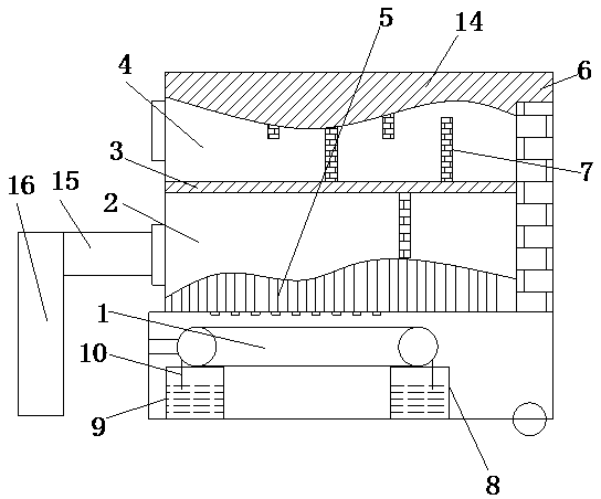
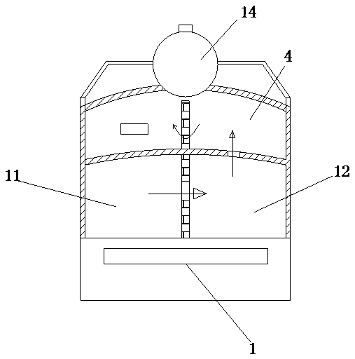
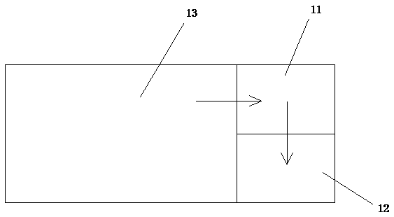
[0020] Example. The waste gasification regenerative combustion device is composed as shown in 1-3, including a water pipe fireplace body 5, a boiler 14 is arranged on the water pipe fireplace body 5, and an upper-layer regenerator 4 and The lower combustion chamber 2, the lower regenerator 2 includes a combustion chamber 13 and a parallel regenerator, a grate 1 is arranged below the combustion chamber 13, and a garbage feeding mechanism is arranged on the side of the combustion chamber 13, and the parallel regenerative The chamber includes a regenerator A11 and a regenerator B12 that communicate with each other, the regenerator A11 communicates with the combustion chamber 13 , and the regenerator B12 communicates with the upper regenerator 4 . It can not only prolong the heat exchange time betw...


PUM


Abstract

The invention discloses a gasification heat-accumulation combustion device for garage. The gasification heat-accumulation combustion device comprises a water pipe wall furnace body, wherein a boiler is arranged on the water pipe wall furnace body; an upper-layer heat-accumulation chamber and a lower-layer heat-accumulation chamber are formed in the water pipe wall furnace body through a water pipe partition layer; the lower-layer heat-accumulation chamber comprises a combustion chamber and shunt-wound heat-accumulation chambers; a fire grate is arranged below the combustion chamber, and a garbage feeding mechanism is arranged at the side part of the combustion chamber; the shunt-wound heat-accumulation chambers include a heat-accumulation chamber A and a heat-accumulation chamber B which are communicated with each other, the heat-accumulation chamber A is communicated with the combustion chamber, and the heat-accumulation chamber B is communicated with the upper-layer heat-accumulation chamber. According to a use method of the gasification heat-accumulation combustion device, garbage is combusted on the fire grate, and hot gas enters the shunt-wound heat-accumulation chambers through a combustion region to warm and remove impurities and simultaneously heat the water pipe wall furnace body and the water pipe partition layer; then hot gas enters the upper-layer heat-accumulation chamber to be subjected to heat accumulation and simultaneously heat the water pipe wall furnace body and the water pipe partition layer, and produced waste heat is used by other equipment.

Description

technical field [0001] The invention relates to the field of garbage heat supply, in particular to a garbage gasification heat storage combustion device and a use method. Background technique [0002] With the improvement of people's living standards, the amount of garbage produced is also increasing, and burning is a conventional way to deal with garbage. Commonly used garbage incinerators are similar in structure to traditional fuel incinerators, both of which have a single combustion chamber. When burning, the garbage is directly poured into the incinerator for combustion. After combustion, the waste gas is directly discharged into the atmosphere through simple purification treatment. . Because the heat of a single combustion chamber is not enough, the garbage cannot be fully burned. The mixture after combustion contains a large amount of inorganic substances that cannot be burned, and also contains a large amount of toxic gases and solid particles with a low combustion ...

Claims


Application Information

Patent Timeline
IPC IPC(8): F23G5/027F23G5/44F23G5/46F24H1/44
CPCF23G5/027F23G5/442F23G5/46F23G2205/121F23G2206/203F24H1/44Y02E20/12
Inventor 李观德
Owner 吴慧文
Why Eureka
Try Eureka