A laser full-face tunneling orientation positioning system

A laser system, directional positioning technology, applied in the direction of active optical measurement device, reference line/plane/sector, measurement device, etc., can solve the problems of poor reliability, difficult maintenance, poor practicability, etc., to achieve strong practicability and operability , to ensure the effect of stable reliability and high work efficiency

Inactive Publication Date: 2017-10-17
SHANXI UNIV
View PDF6 Cites 0 Cited by
  • Summary
  • Abstract
  • Description
  • Claims
  • Application Information

AI Technical Summary

Problems solved by technology

[0002] In the process of roadway excavation, in order to make the direction of the roadway advance according to the required parameters of the design, the traditional method is to use a single-point laser pointer to emit a beam of laser light to form a spot in the middle of the section at the front end of the roadway for reference. Operators excavate based on experience, measure with a tape after the roadway is formed, and then carry out secondary correction and excavation. This method not only has poor roadway forming quality and reliability, but also takes time and labor. It can no longer meet the requirements of standardization and rapid excavation.
[0003] With the development of technology, researchers at home and abroad have proposed to install the laser receiver on the roadheader to carry out directional excavation by controlling the direction of the cutting head of the roadheader. This method is due to the inclination, deviation, and complex conditions of the roadheader The reason is that the laser receiver on the fuselage is difficult to receive the guided laser beam, and the method has complex structure, difficult maintenance and poor practicability

Method used


Image

  • A laser full-face tunneling orientation positioning system
  • A laser full-face tunneling orientation positioning system
  • A laser full-face tunneling orientation positioning system

Examples


Embodiment Construction

[0028] The present invention will be further described below in conjunction with accompanying drawing.

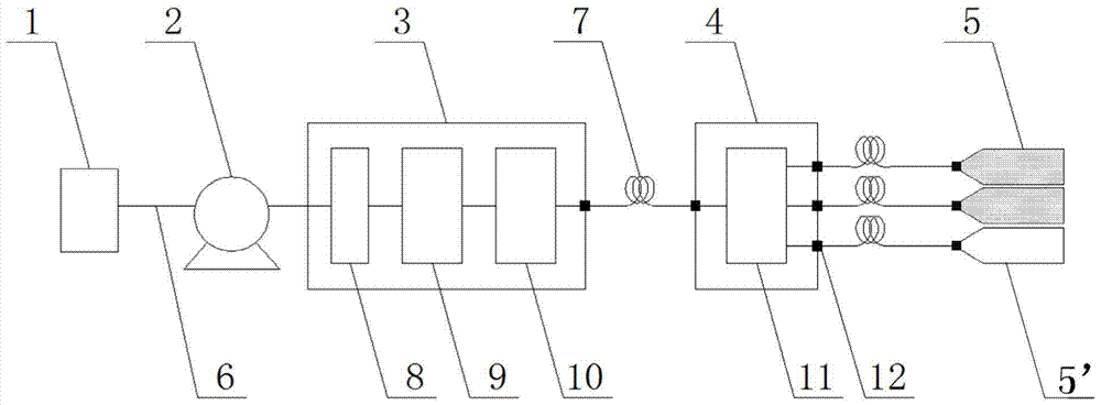
[0029] figure 1 A green laser full-face excavation directional positioning system shown includes: an all-solid-state green laser system 3, a laser beam splitting system 4, two first laser shaping systems 5, a second laser shaping system 5', and a UPS power supply 1. Explosion-proof switch 2, explosion-proof cable 6, optical fiber 7, fiber optic coupler 12; the UPS power supply 1 and the all-solid-state laser system 3 are connected with an explosion-proof cable 6 and provided with an explosion-proof switch 2; the all-solid-state green The optical laser system 3 outputs a bunch of green laser through the optical fiber 7 and enters the laser beam splitting system 4, and the laser beam splitting system 4 outputs three beams of laser light, which are respectively input to two first laser shaping systems 5 and a second laser shaping system through three optical fibers. System 5'...


PUM


Abstract

The invention discloses an orientating and positioning system for laser whole-section advancing. The orientating and positioning system comprises an all-solid-state laser system, a laser beam splitting system, two first laser shaping systems, a second laser shaping system, a UPS power source, an anti-explosion switch, an anti-explosion cable, optical fibers and optical fiber couplers; the all-solid-state laser system outputs a laser which is input into the laser beam splitting system through an optical fiber, the laser beam splitting system outputs three lasers which are input into the two first laser shaping system and the second laser shaping system through three optical fibers; the two first laser shaping systems output two vertical linear light sources in a shaping mode; the second laser shaping system outputs an arc linear light source in a shaping mode; the two vertical linear light sources and the arc linear light source form a complete section design profile on the section of the most front portion of an advancing roadway, a driver of a heading machine can conduct rapid orientating and positioning interception cutting according to a section profile light source, a benchmark basis is provided for accurate interception cutting of the advancing roadway, and smooth conduction of advancing operation is guaranteed.

Description

technical field [0001] The invention relates to an orientation and positioning system, in particular to a laser full-section excavation orientation and positioning system suitable for roadway excavation. Background technique [0002] In the process of roadway excavation, in order to make the direction of the roadway advance according to the required parameters of the design, the traditional method is to use a single-point laser pointer to emit a beam of laser light to form a spot in the middle of the section at the front end of the roadway for reference. Operators excavate based on experience, measure with a tape after the roadway is formed, and then carry out secondary correction and excavation. This method not only has poor roadway forming quality and reliability, but also is labor-intensive and time-consuming. It can no longer meet the requirements of standardization and rapid excavation. [0003] With the development of technology, researchers at home and abroad have pro...

Claims


Application Information

Patent Timeline
Patent Type & Authority Patents(China)
IPC IPC(8): G01C15/00
CPCG01C15/004
Inventor 刘建丽
Owner SHANXI UNIV
Why Eureka
Try Eureka