Light path coupling device and fluorescence temperature sensing optical system

A coupling device and fluorescence technology, applied in the field of fluorescence temperature sensing optical systems, can solve the problems such as the fluorescence excitation light source and the fluorescence detector cannot be combined on the same circuit board, the stability and reliability are weak, and the contact is poor, so as to reduce the Poor contact, improving stability and reliability, preventing component damage

Active Publication Date: 2016-04-20
ZHUHAI OUSENSI TECH CO LTD
View PDF8 Cites 10 Cited by
  • Summary
  • Abstract
  • Description
  • Claims
  • Application Information

AI Technical Summary

Problems solved by technology

However, due to the different directions of the optical paths of the fluorescence excitation light source and the fluorescence detector, the fluorescence excitation light source and the fluorescence detector cannot be combined on the same circuit board, and the combination is more complicated during product installation.
And the line connection of multiple circuit boards is prone to poor contact, etc., and the stability and reliability of the product are weak

Method used


Image

  • Light path coupling device and fluorescence temperature sensing optical system
  • Light path coupling device and fluorescence temperature sensing optical system
  • Light path coupling device and fluorescence temperature sensing optical system

Examples


Embodiment Construction

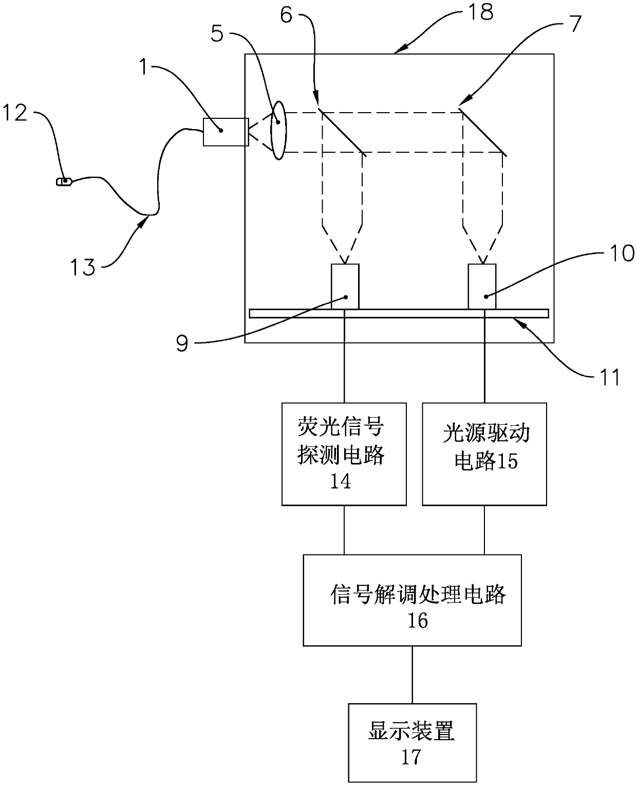
[0027] Such as figure 1 As shown, the fluorescent temperature sensing optical system provided by the present invention includes a fluorescent optical fiber temperature measuring probe 12 , a light source driving circuit 15 , a fluorescent signal detection circuit 14 , a signal demodulation processing circuit 16 , a display device 17 and an optical coupling device 18 . Wherein, the optical path coupling device 18 includes a fluorescence excitation light source 10 and a fluorescence detector 9 . The fluorescence excitation light source 10 and the fluorescence detector 9 are arranged on the same surface of the same circuit board 11 , and the fluorescence excitation light source 10 and the fluorescence detector 9 are arranged in parallel. The light source driving circuit 15 is electrically connected to the fluorescence excitation light source 10 and sends a light source driving signal to the fluorescence excitation light source 10 . The fluorescence signal detection circuit 14 is...


PUM


Abstract

The invention provides a light path coupling device and a fluorescence temperature sensing optical system. The light path coupling device comprises an optical fiber splice, a fluorescence exciting light source, a fluorescence detector and a filter. The fluorescence exciting light source and the fluorescence detector are arranged on the same surface of the same circuit board. The fluorescence detector and the filter are arranged oppositely. Coupling lenses are arranged on a light path of the filter and a light path of the optical fiber splice. The filter and the coupling lenses are located on the light paths between the fluorescence exciting light source and the optical fiber splice. The light path coupling device further comprises a box. An optical mirror groove is formed in the box. The filter is located in the optical mirror groove. A through hole is formed in the box. The optical fiber splice and the coupling lenses are located in the through hole. The system comprises a fluorescence optical fiber temperature detecting probe, a light source drive circuit, a fluorescence signal probing circuit, a signal demodulation processing circuit, a display device and the light path coupling device. The fluorescence temperature sensing optical system is convenient to install, and high in stability and measurement precision.

Description

technical field [0001] The invention relates to the field of optical fiber sensing, in particular to an optical path coupling device and a fluorescent temperature sensing optical system using the optical path coupling device. Background technique [0002] The temperature measurement principle of the existing optical fiber sensing technology is based on the material properties of rare earth fluorescent substances. After some rare earth fluorescent substances are irradiated and excited by ultraviolet rays, they emit line-like spectra in the visible spectrum, that is, fluorescence and afterglow (afterglow is the excitation stop). after the glow). The decay time constant of fluorescence afterglow is a single-valued function of temperature, and generally the higher the temperature, the smaller the time constant. As long as the value of the time constant is measured, the temperature can be calculated. The biggest advantage of using this method to measure temperature is that the ...

Claims


Application Information

Patent Timeline
Patent Type & Authority Applications(China)
IPC IPC(8): G01K11/32
CPCG01K11/3213G01K11/32
Inventor 吴占民郑浩奇缪爱俊
Owner ZHUHAI OUSENSI TECH CO LTD
Why Eureka
Try Eureka