
A DC microgrid group energy storage optimization and coordinated control method

A DC micro-grid and coordinated control technology, applied in parallel operation of DC power supplies, load balancing in DC networks, etc., can solve problems that need to be studied, achieve the effect of speeding up the balance speed and improving the quality of the bus voltage

Active Publication Date: 2018-06-29
SHANGHAI UNIVERSITY OF ELECTRIC POWER
View PDF4 Cites 3 Cited by
  • Summary
  • Abstract
  • Description
  • Claims
  • Application Information

AI Technical Summary

Problems solved by technology

Literature (Zhou Niancheng, Jin Ming, Wang Qianggang, et al. Multi-microgrid system hierarchical coordination control strategy with series and parallel structure [J]. Electric Power System Automation, 2013, 37(12): 13-18) proposed a multi-microgrid system The tie-line power and grid-connected synchronous coordinated control strategy can reduce the amplitude difference, frequency difference and phase difference of the voltage on both sides of the closing switch to the synchronization range. Microgrid system operation control still needs to be studied
However, few existing researches involve the coordinated control of multiple sub-microgrid systems in different operating states, which is crucial for the normal operation of multi-sub-microgrid systems and efficient and reliable power supply for loads (Liang Che, MohammadShahidehpour.DC Microgrids : Economic Operation and Enhancement of Resilience by Hierarchical Control. IEEE Trans. on Smart Grid, 2014, 5(5): 2517-2526)

Method used


Image

  • A DC microgrid group energy storage optimization and coordinated control method
  • A DC microgrid group energy storage optimization and coordinated control method
  • A DC microgrid group energy storage optimization and coordinated control method

Examples


Embodiment Construction

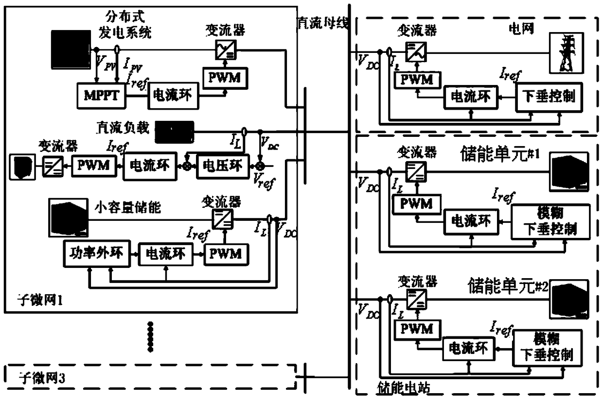
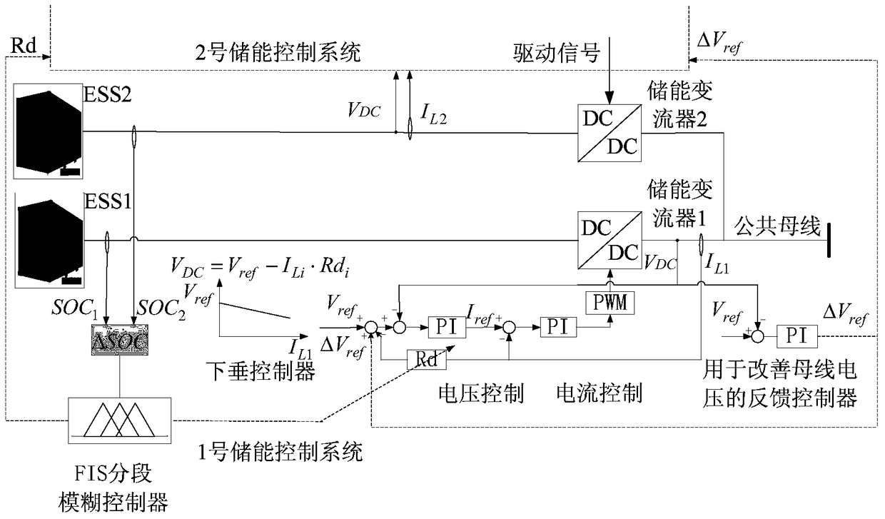
[0048] In this paper, a two-layer coordinated control strategy is adopted to control the stable and reliable operation of the microgrid group. The bottom layer adopts decentralized control. Under this control, MPPT is used to control distributed power generation systems such as photovoltaics to output electric energy at maximum power. The small-capacity energy storage system in the sub-microgrid adopts an improved power control method to automatically allocate load power requirements and reach the safety capacity limit. When disconnecting from the microgrid to protect the energy storage, the load can be connected to the DC bus directly or through a DC / DC converter after power conversion according to specific requirements. Each energy storage unit in the energy storage power station adopts a segmented fuzzy droop control strategy to dynamically distribute load power, and compensates the bus voltage drop caused by droop control through voltage feedback control. The upper layer c...


PUM


Abstract

The invention relates to an energy storage optimization and coordination control method for a direct-current micro grid group. When multiple sub micro grids are operated in parallel, an energy storage system in each sub micro grid automatically adjusts power distribution according to the maximum charging and discharging power and the state of charge (SOC) of the corresponding energy storage system, and therefore the safety of the energy storage systems is improved while distributed generated power fluctuation can be smoothed and the bus voltage quality can be improved; when the energy storage systems of all the sub micro grids cannot effectively buffer the system power supply and demand, an energy storage power station needs to be connected to control stabilization of the bus voltage. According to the energy storage optimization and coordination control method for the direct-current micro grid group, the virtual impedance of droop controllers of all energy storage units in the energy storage power station is adjusted by adopting fuzzy control to achieve automatic distribution of the power among the different energy storage units and SOC balance, fuzzy input is segmented, the SOC balancing speed of the fuzzy input in different ranges is increased by adopting fuzzy control, bus voltage drop caused by droop control is compensated by adopting a bus voltage feedback control method, and the bus voltage quality is improved.

Description

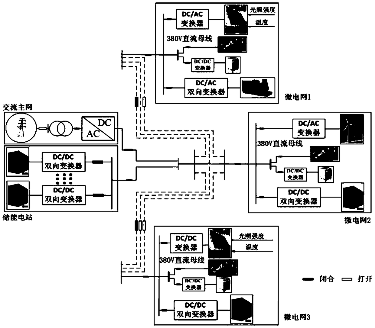
technical field [0001] The invention relates to a design technology of a micro-grid coordination controller, in particular to a DC micro-grid group energy storage optimization and coordination control method. Background technique [0002] As an autonomous system with self-control and self-energy management, microgrid can work in both grid-connected mode and off-grid mode (Wang Chengshan, Wu Zhen, Li Peng. Research on key technologies of microgrid[J]. Electrotechnical Technology Journal, 2014, 29(2):1-12). like figure 1 It is the structure diagram of the microgrid system. Compared with the AC microgrid, the DC microgrid formed by establishing a DC transmission line in the microgrid and connecting various distributed power sources and energy storage systems can improve the utilization rate of the converter and reduce losses. It is conducive to the complementary advantages and coordinated control among micro-sources (Wang Yi, Zhang Lirong, Li Heming, etc. Voltage layered coor...

Claims


Application Information

Patent Timeline
Patent Type & Authority Patents(China)
IPC IPC(8): H02J1/10H02J1/14
CPCH02J1/10H02J1/14
Inventor 米阳吴彦伟马超韩云昊杨慧霞纪宏澎
Owner SHANGHAI UNIVERSITY OF ELECTRIC POWER
Learn More