Friction welding method for copper and aluminum end faces

A technology of friction welding and end face, which is applied in the direction of welding equipment, non-electric welding equipment, metal processing equipment, etc., can solve the problems of low joint area, low joint strength, unstable friction coefficient, etc., to increase the joint area, improve the joint strength, Effect of reducing oxide impurities

Inactive Publication Date: 2016-04-27
JIANGSU JIAMENG ELECTRICAL EQUIP
View PDF7 Cites 15 Cited by
  • Summary
  • Abstract
  • Description
  • Claims
  • Application Information

AI Technical Summary

Problems solved by technology

[0006] The technical problem to be solved by the present invention is to overcome the defects of the friction welding method in the prior art that the friction coefficient is unstable, the joint area is low, and the joint strength is low due to the presence of oxide impurities, and to provide a welding method with a more stable friction coefficient and higher joint strength. Friction welding method of copper and aluminum end faces

Method used


Image

  • Friction welding method for copper and aluminum end faces
  • Friction welding method for copper and aluminum end faces
  • Friction welding method for copper and aluminum end faces

Examples


Embodiment 1

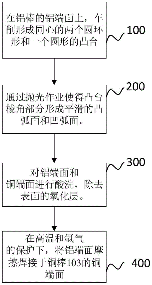
[0042] figure 1 It is the flow chart of the friction welding method of the copper-aluminum end face of embodiment 1 of the present invention, as figure 1 As shown, the friction welding method of the copper-aluminum end face involved in embodiment 1 includes the following steps:

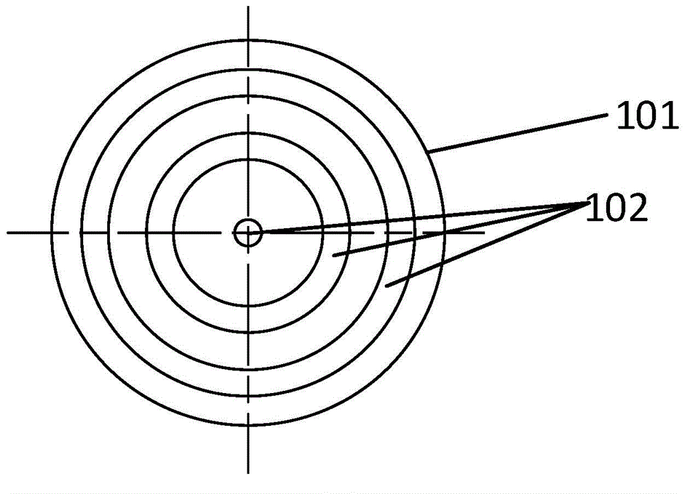
[0043] Step 100, on the aluminum end surface of the object to be welded (in this embodiment, an aluminum rod), machine tool turning process forms two concentric circular rings and a circular boss, and the section of the boss is the lower bottom and the aluminum end surface connected trapezoids. figure 2 It is the top view of the aluminum end face of embodiment 1, as figure 2 As shown, the aluminum end surface of the aluminum rod 101 is provided with a boss 102 .

[0044] Step 200 , using a polishing machine to polish the corners (including the angle between the waist and the bottom surface) of the boss until all the parts with corners form smooth arc surfaces.

[0045] Step 300, pickling the alu...

Embodiment 2

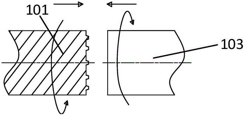
[0048] Figure 4 It is the flowchart of the friction welding method of the copper-aluminum end face of embodiment 2, figure 2 It is the top view of the aluminum end face of embodiment 2, image 3 It is the structural representation of the joint of the aluminum end face and the copper end face of embodiment 2, as Figure 2~4 As shown, the friction welding method of the copper-aluminum end face that embodiment 2 involves includes the following steps:

[0049] Step 1. On the aluminum end face of the object to be welded (in this embodiment, an aluminum rod), two concentric circular rings and a circular boss are formed by lathe turning. The cross section of the boss is the lower bottom and the aluminum end face. connected trapezoids. like figure 2 As shown, the aluminum end surface of the aluminum rod 101 is provided with a boss 102 .

[0050]Step 11, turning the copper end surface of the copper rod 103 to form a groove (not shown in the figure) that matches the shape of the...


PUM

PropertyMeasurementUnit
Thicknessaaaaaaaaaa

Abstract

The invention discloses a friction welding method for copper and aluminum end faces. The method comprises the following steps that S1, a plurality of concentric ring-shaped or round bosses are formed on the copper or aluminum end face of a to-be-welded object with the copper or aluminum end face, and the section of each boss is in the shape of a trapezoid with the lower bottom connected with the copper or aluminum end face; S2, edges and corners of the bosses are removed; S3, acid pickling is conducted on the copper or aluminum end face, and a surface oxide layer is removed; and S4, the copper or aluminum end face is connected to another to-be-welded object with the copper or aluminum end face through friction welding. The copper and aluminum end faces are provided with the bosses and grooves, the bosses and the grooves are spliced, and thus the splicing area is increased; furthermore, the copper and aluminum end faces are treated before and during friction welding, the quantity of oxide impurities is reduced, and thus the splicing strength is improved.

Description

technical field [0001] The invention relates to a friction welding method, in particular to a friction welding method for copper-aluminum end faces. Background technique [0002] Friction welding refers to that under the action of pressure, the temperature of the interface and its vicinity increases through the friction of the interface to be welded, the deformation resistance of the material is reduced, the plasticity is improved, and the oxide film of the interface is broken, accompanied by plastic deformation and flow of the material, through A solid-state welding method that realizes connection by interface diffusion and recrystallization metallurgical reaction. In this method, for a given material, under the conditions of sufficient friction pressure and sufficient movement speed, the temperature of the material to be welded continues to rise, and with the progress of the friction process, the workpiece also produces a certain amount of deformation, thereby realizing th...

Claims


Application Information

Patent Timeline
IPC IPC(8): B23K20/12B23K20/14B23K20/24
Inventor 施希锋王亚如刘建
Owner JIANGSU JIAMENG ELECTRICAL EQUIP
Why Eureka
Try Eureka