Three-dimensional circular light system

A light and ring technology, applied in the field of optical fiber systems, to achieve the effect of high electro-optical efficiency

Inactive Publication Date: 2016-04-27
QINGDAO LASENCE
View PDF6 Cites 0 Cited by
  • Summary
  • Abstract
  • Description
  • Claims
  • Application Information

AI Technical Summary

Problems solved by technology

[0003] In addition, in engineering applications, three-dimensional light indicators are often required, and only one-dimensional lines after reflection by the axicon mirror cannot meet the needs

Method used


Image

  • Three-dimensional circular light system
  • Three-dimensional circular light system

Examples


Embodiment 1

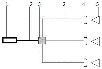
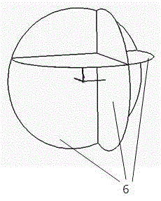
[0021] structure see figure 1 The light beam emitted by the laser point light source of the laser 1 is firstly coupled into the optical fiber 2 through a coupling mirror. After the three beams of laser light pass through the independent lens group 4 at the end, the divergence angle is compressed to a near-parallel light, and the light spot at this point is then passed through the reflective conical mirror 5 to obtain a 360° ring-shaped light. The ring-shaped light surface 6 is as figure 2 shown. The three laser beams are respectively arranged along the three-dimensional X, Y, and Z axis directions, so that the planes where the outgoing ring light rays are located are perpendicular to each other. In this embodiment, the laser is set as a semiconductor laser, and the optical fiber is set as a single-mode optical fiber.

Embodiment 2

[0023] The difference between this embodiment and Embodiment 1 is that the laser in this embodiment is set as a solid-state laser, and the optical fiber is set as a multimode optical fiber.

Embodiment 3

[0025] The difference between this embodiment and Embodiment 1 is that the laser in this embodiment is set as a gas laser.

[0026] The wavelength of the laser used can be selected according to the needs of visible light or ultraviolet and infrared light for special purposes;

[0027] In the actual application of the three-dimensional light system of the present invention, more than one line may be required in a certain dimension, and ring light at a special angle may also be used, so the number of optical fiber beam splitting is not limited to three.


PUM


Abstract

The invention relates to an optic fiber system, in particular to a three-dimensional circular light system. Laser point light of the three-dimensional circular light system is split by an optical fiber system and then reformed to suitable divergent degrees, and beams then pass through a reflecting cone to form 360-degree circular light. The optical fiber splitting system can be divided into multiple beams, so that three-dimensional circular light spots may be implemented from a single laser source. This three-dimensional circular light system comprises a laser, a lens set and the cone, and the light of the laser reaches the laser set through a light path and then reaches the cone, forming the circular light.

Description

technical field [0001] The invention relates to an optical fiber system, in particular to a three-dimensional ring light system. Background technique [0002] The laser line throwing instrument is widely used in construction projects, and it has the functions of the original level and theodolite marking. It uses laser lines to accurately project the working alignment on the work object, making the construction process more convenient and time-saving. However, to form a 360° circular line, four or more inline light sources are required, and the module is required to have high stability and high adjustment accuracy. Using the 360° ring module of the axicon mirror alone can realize the previous requirements, and because there is only one module, it has obvious advantages in adjustment and stability. [0003] In addition, in engineering applications, three-dimensional light indicators are often required, and only one-dimensional lines after reflection by the axicon mirror cann...

Claims


Application Information

Patent Timeline
Patent Type & Authority Applications(China)
IPC IPC(8): G01C15/00
CPCG01C15/004
Inventor 马长勤贾玉昌亓玉凯
Owner QINGDAO LASENCE
Why Eureka
Try Eureka