Multi-antenna joint optimization clutter suppression method based on fractional time delay estimation

A technology of joint optimization and clutter suppression, applied in radio wave measurement systems, instruments, etc., can solve the problems of not fully mining the information of multi-domain signals, general clutter suppression performance, and limited clutter suppression performance, so as to improve detection. performance, improve detection capabilities, and enhance the effect of detection performance

Active Publication Date: 2016-04-27
THE PLA INFORMATION ENG UNIV
View PDF2 Cites 19 Cited by
  • Summary
  • Abstract
  • Description
  • Claims
  • Application Information

AI Technical Summary

Problems solved by technology

The method of adaptive interference cancellation is to use the correlation between the clutter signal in the echo channel and the direct wave signal in the reference channel, and through an adaptive method, the weighted reference signal and the mixed clutter signal are approximated, and finally To achieve the purpose of clutter suppression, this kind of algorithm has the problem of convergence speed, and the clutter suppression performance is general; the method of extended cancellation is actually to project the monitoring channel...

Method used


Image

  • Multi-antenna joint optimization clutter suppression method based on fractional time delay estimation
  • Multi-antenna joint optimization clutter suppression method based on fractional time delay estimation
  • Multi-antenna joint optimization clutter suppression method based on fractional time delay estimation

Examples


Embodiment 1

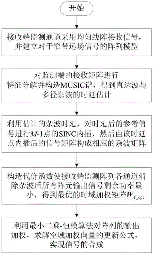
[0030] Embodiment one, see Figure 1~2 As shown, a multi-antenna joint optimal clutter suppression method based on fractional time delay estimation, specifically includes the following steps:

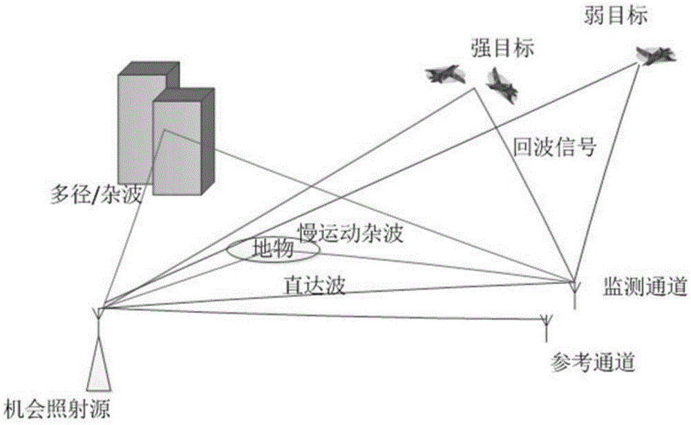
[0031] Step 1. When passively detecting the target, the monitoring channel of the passive radar receiving end adopts a uniform linear array

[0032] Receive signals and build an array model of narrowband far-field signals;

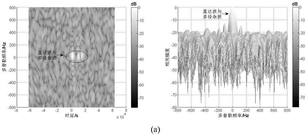
[0033] Step 2. Carry out eigendecomposition to the autocorrelation matrix of array model matrix, construct MUSIC spectrum, obtain the delay estimation of direct wave and multipath clutter;

[0034] Step 3. Utilize the time delay estimation obtained in step 2, carry out the SINC function interpolation of M-1 point to the reference signal after the time delay, the signal matrix after the interpolation constitutes corresponding clutter matrix;

[0035] Step 4. By constructing a cost function, after eliminating the clutter in each channel of the receiving end monitori...

Embodiment 2

[0037] Embodiment two, see Figure 1~2 , a multi-antenna joint optimal clutter suppression method based on fractional time delay estimation, which specifically includes the following steps:

[0038] Step 1. When passively detecting the target, the monitoring channel of the passive radar receiving end adopts a uniform linear array to receive the signal, and establishes an array model of the narrowband far-field signal. The array model is expressed as: X surv (t)=AS(t)+N surv (t), where A=[α(θ 1 )α(θ 2 )...α(θ D )] is the flow pattern matrix of the L×D dimensional array, L is the number of array elements, and D is the total number of direct waves, multipath clutter and target echoes in the monitoring channel. If a uniform linear array is used, the flow pattern matrix The steering vector of is expressed as: is the position of the array element, θ i is the direction of the signal, λ is the wavelength; S(t)=[s d (t)s mp1 (t)s mp2 (t)...s eco (t)] T is a D×1-dimensional ...


PUM


Abstract

The present invention relates to a multi-antenna joint optimization clutter suppression method based on fractional time delay estimation. A receiving end monitoring channel receives a signal by using a uniform linear array, and a signal array model is established; the self-correlation matrix of an array model matrix is subjected to feature decomposition, a MUSIC spectrum is constructed, and the time delay estimation of a direct wave and a multipath clutter is obtained; the time delay signal after time delay is subjected to SINC function interpolation, and a corresponding clutter matrix is constructed; through constructing a cost function, an optimal time-domain weighting matrix WT_opt is obtained; the output of the array is weighted by using a least squares-constant modulus algorithm, a spatial weighting vector ws is solved, and the signal combination and output are carried out. According to the method, the time domain and spatial domain information of the signal are fully dug, the correlation of the signals in different array elements is monitored by using a receiving end, through the least squares-constant modulus algorithm, the noise and residual clutter outside a target echo coming direction are subjected to attenuation, the clutter rejection ratio of the output signal is raised, and the detection performance of a weak object can be improved at the same time.

Description

technical field [0001] The invention relates to the field of clutter suppression, in particular to a multi-antenna joint optimization clutter suppression method based on fractional time delay estimation. Background technique [0002] Passive radar uses an external non-cooperative radiation source as a signal source to detect and locate the detection target. Because it does not emit electromagnetic waves, it has good concealment and anti-reconnaissance performance; at the same time, it does not need emitting equipment, which saves manufacturing costs. In view of the above advantages, the research of passive radar system has been widely concerned by scholars at home and abroad in recent years. The external radiation sources used generally include FM broadcast signals, mobile communication signals, TV broadcast signals and satellite signals. Generally, there are two channels at the receiving end of the passive radar, the monitoring channel and the reference channel. Since th...

Claims


Application Information

Patent Timeline
IPC IPC(8): G01S7/02
CPCG01S7/023
Inventor 吴瑛吴江翟永惠杨宾张莉王鼎唐涛王云龙
Owner THE PLA INFORMATION ENG UNIV
Why Eureka
Try Eureka