High-voltage start-up circuit

A high-voltage startup and startup capacitor technology, applied in emergency protection circuit devices, electrical components, output power conversion devices, etc., can solve problems such as heat accumulation, thermal damage to startup circuits, and virtual welding of startup capacitors, reducing short circuits. Power consumption, avoid overheating damage, avoid overvoltage damage effect

Active Publication Date: 2016-04-27
SHENZHEN NANYUN MICROELECTRONICS CO LTD
View PDF5 Cites 12 Cited by
  • Summary
  • Abstract
  • Description
  • Claims
  • Application Information

AI Technical Summary

Problems solved by technology

For example, the input voltage of the power supply is 300V, the high-voltage starting current is 2mA, and the high-voltage starting circuit will generate heat with a power of 600mW. If the heat continues to accumulate for a long time, it will cause thermal damage to the starting circuit
[0007] 2. The hazards of starting capacitor virtual welding
If there is no such function, as soon as the controller is under-voltage locked out, the startup circuit will immediately charge the startup capacitor again, and the controller will start up again, and the power supply will immediately work in the case of a short circuit at the output end, causing the heat to accumulate for a long time, resulting in power failure. heat damage

Method used


Image

  • High-voltage start-up circuit
  • High-voltage start-up circuit
  • High-voltage start-up circuit

Examples


Embodiment 1

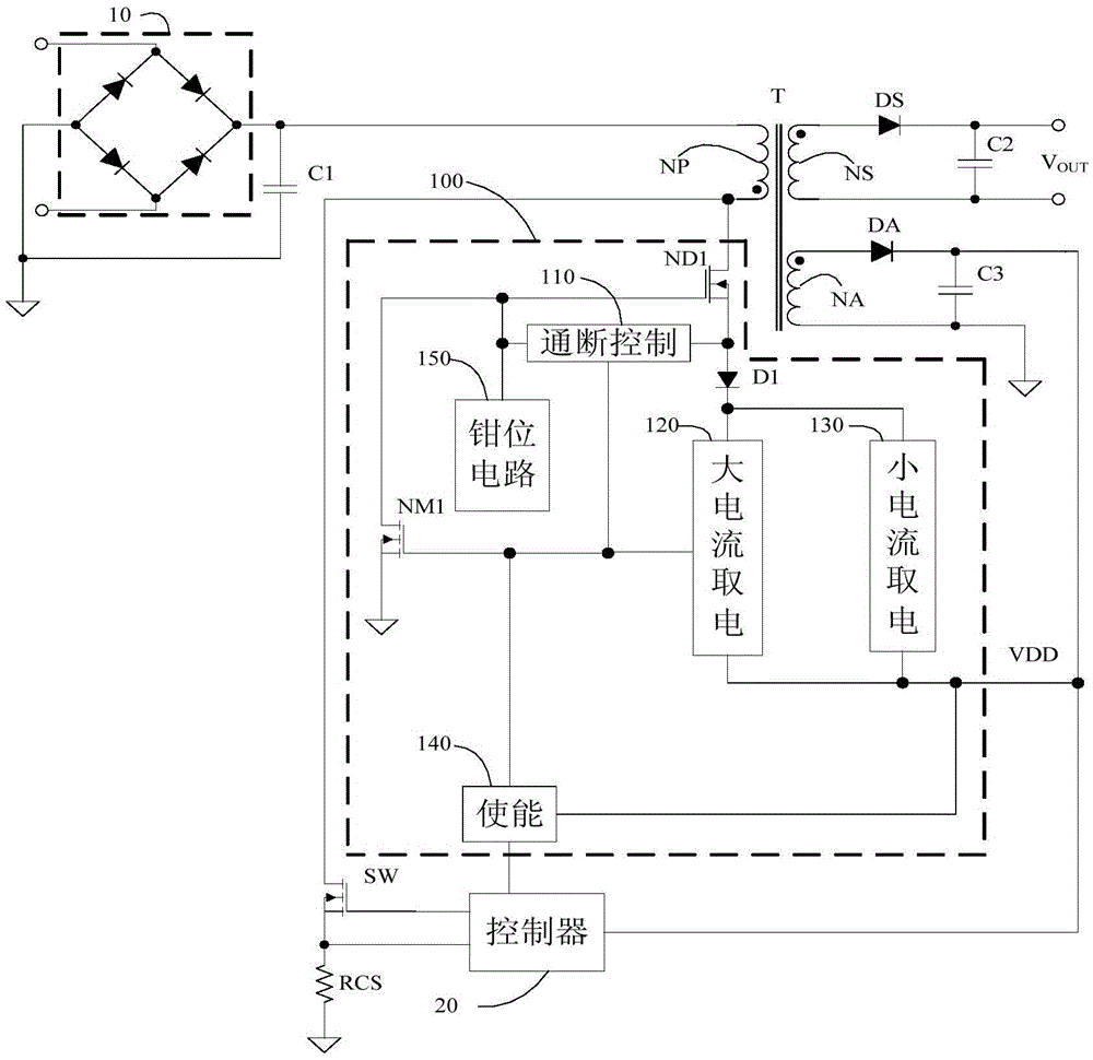
[0046] figure 2 Shown is the structural diagram of the high-voltage start-up circuit 100 of Embodiment 1 of the present invention, which is connected with the rectifier 10 and the transformer T to control the on-off and magnitude of the start-up current, which not only allows the controller 20 to start under normal conditions, but also Each circuit can be protected from being damaged under abnormal conditions. The high-voltage start-up circuit 100 includes a transistor ND1, an on-off control module 110, a diode D1, a large-current power-taking module 120, a small-current power-taking module 130, an enabling module 140, a clamping circuit 150, and an NMOS transistor NM1.

[0047] When the power supply is just powered on, the voltage of the power supply terminal VDD is 0V, and the enabling module 140 outputs a low-level signal, so that the NMOS transistor NM1 is turned off, the on-off control module 110 is turned on, and the transistor ND1 is turned on, so that the input power ...

Embodiment 2

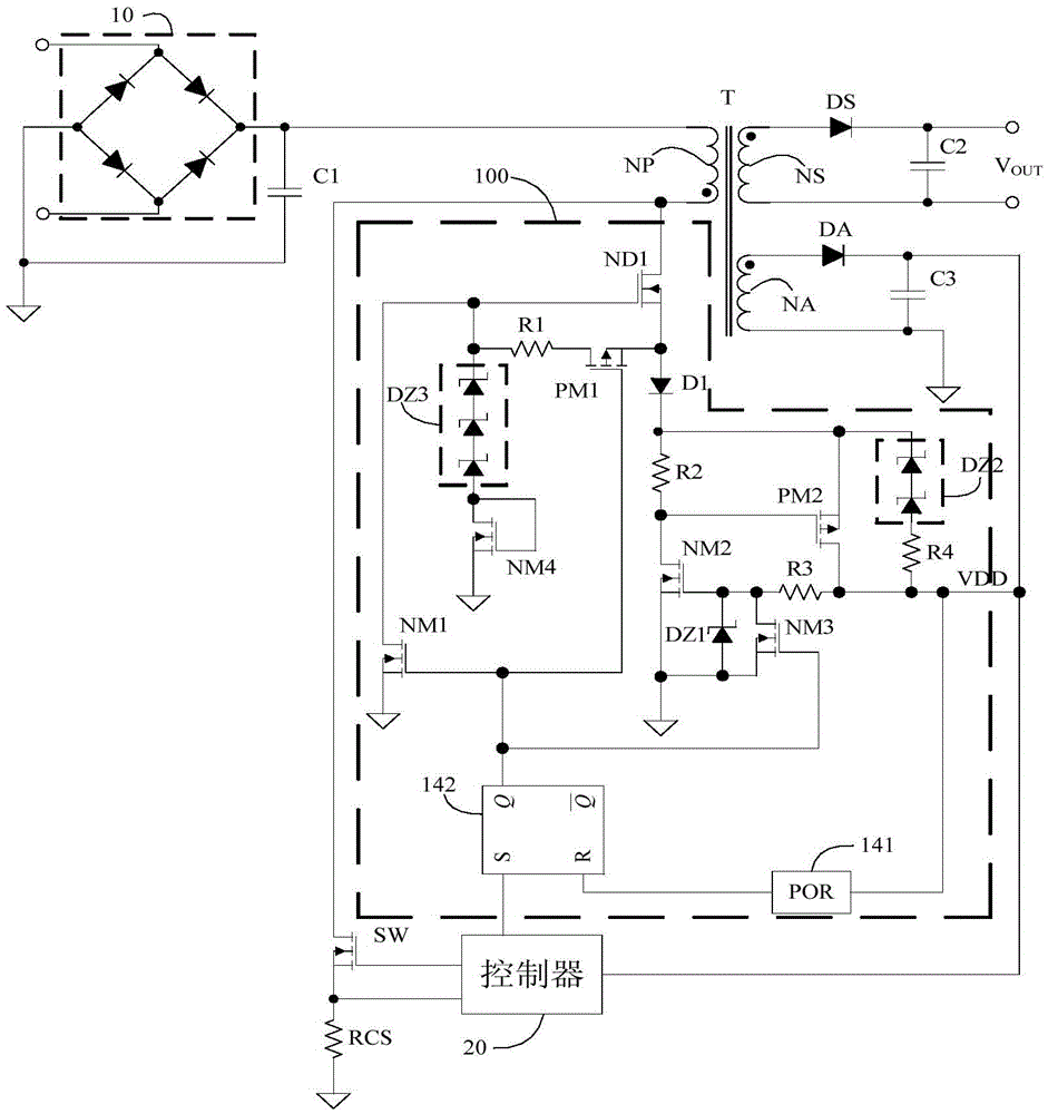
[0085] Figure 5 Shown is a detailed circuit schematic diagram of the high-voltage starting circuit of Embodiment 2 of the present invention. Such as Figure 5 As shown, different from Embodiment 1, in the process adopted in Embodiment 2, the threshold voltage of transistor ND1 is similar to the threshold voltage of PMOS transistor PM1, there is a risk that the on-off control module 210 cannot be turned on during the startup process, and then It affects the performance of the high-voltage starting circuit 200 , so in order to ensure the normal use of the high-voltage starting circuit 200 , in Embodiment 2, the on-off control module 210 includes a diode D2 and a resistor R1 , and the PMOS transistor PM1 is not used. One end of the resistor R1 is connected to the gate of the transistor ND1 , the other end of the resistor R1 is respectively connected to the source of the transistor ND1 and the cathode of the diode D2 , and the anode of the diode D2 is connected to the output of ...

Embodiment 3

[0089] Figure 6 Shown is a schematic structural diagram of a high voltage starting circuit 300 according to Embodiment 3 of the present invention. Such as Figure 6 As shown, the difference from Embodiment 1 is that the enabling module 340 of the high-voltage starting circuit 300 can control the high-voltage starting circuit 300 to cut off the charging current according to the received enabling signal from other circuits except the controller 20 . Other working processes and working principles of the high-voltage starting circuit 300 are the same as those in Embodiment 1, and will not be repeated here.


PUM


Abstract

The invention discloses a high-voltage start-up circuit, which can directly take electricity from an input voltage, and is used for charging a start-up capacitor which is externally connected with a power supply end of a controller to start the controller. The high-voltage start-up circuit disclosed by the invention has a plurality of protective functions; and after a power supply is broken down, the controller can also be restarted by high-voltage startup disclosed by the invention under the premise of ensuring the reliability of the power supply and the controller.

Description

technical field [0001] The invention relates to a switching power supply, in particular to a high-voltage starting circuit of the switching power supply. Background technique [0002] Generally speaking, the power supply circuit will include a start-up circuit to start the controller when the power supply is powered on, drive the transformer to convert the voltage, and realize the normal operation of the power supply. At this time, the power supply of the controller can be provided by the auxiliary winding. [0003] Such as figure 1 As shown, in the traditional power starting circuit, a large resistor RST (usually in the order of megohm) is connected between the power input voltage and the starting capacitor to provide a current to charge the capacitor to complete the startup of the controller. This large resistance will cause unnecessary waste of power consumption after the start-up process is completed. This point is described in detail in the Chinese patent with the pub...

Claims


Application Information

Patent Timeline
Patent Type & Authority Applications(China)
IPC IPC(8): H02M1/36H02H7/12H02M1/32
CPCH02H7/12H02H7/1213H02M1/32H02M1/36
Inventor 唐盛斌符威
Owner SHENZHEN NANYUN MICROELECTRONICS CO LTD
Why Eureka
Try Eureka