

An automatic focusing device and system
A technology of automatic focusing and focusing value, applied in focusing devices, parts and installations of TV systems, etc., can solve the problem of high cost of telescopes, and achieve the effect of shortening focusing time, reducing costs, and improving focusing accuracy.
- Summary
- Abstract
- Description
- Claims
- Application Information
AI Technical Summary
Problems solved by technology
Method used
Image

Examples
Embodiment 1
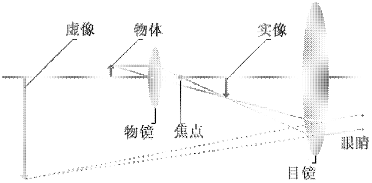
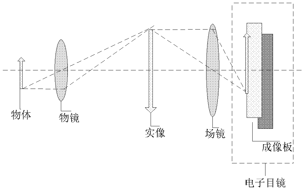
[0051] Such as figure 1 As shown, the traditional microscope or telescope device magnifies the real image formed by the objective lens again, so as to form a clear virtual image at the apparent distance. This kind of device can only be used for observation, but cannot carry out image analysis and preservation. Electron microscopes and telescopes make up for this defect very well. figure 2 Shows how electron microscopes and electron telescopes work. Although traditional electron microscopes and electronic telescopes convert traditional optical signals into digital signals and realize image analysis and preservation, they lack autofocus functions (here does not include microscopes and telescopes with autofocus functions, because they have autofocus functions). The principle of realizing the autofocus function of the optical system with focusing function is different from that of the present invention, which is introduced in the background technology). The present invention ai...
Embodiment 2
[0073] The embodiment that the second technical problem to be solved by the present invention takes is as follows:
[0074] In traditional microscopes and telescopes, since the working distance is fixed, if the height of the measured object changes, the image will be unclear.
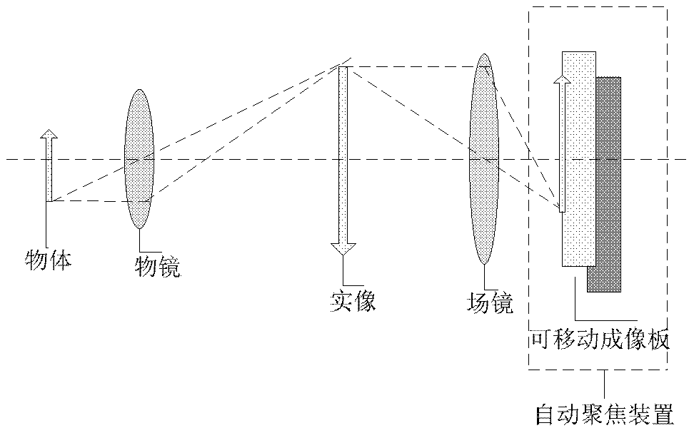
[0075] Such as image 3 and Figure 6 As shown, this embodiment differs from conventional electron microscopes and electron telescopes in that the object distance u is variable. According to the optical imaging formula 1, f is fixed, and the image distance v is variable (from v to v'), so the object distance u is variable (from u to u'). This means that even if the height of the measured object changes, the main control unit inside the autofocus device can execute the focus search algorithm to automatically control the movement of the Sensor board to change the image distance (from v to v') to make the image clear.
[0076] The implementation steps of automatic focusing are the same as those in Embodim...
Embodiment 3
[0078] Figure 8 It is a schematic block diagram of an optical system including an auto-focusing device. The optical system can be an auto-focusing microscope system, an auto-focusing telescope system, or an auto-focusing industrial camera, which is composed of an auto-focusing device, a front-end optical system and external equipment. Among them, the autofocus device in Embodiment 3 synthesizes the autofocus functional modules of Embodiment 1 and Embodiment 2, and correspondingly introduces the implementation of specific hardware entities of some functional modules. For example, in Embodiment 3, the image The data processing unit 226a and the focus value calculation unit 226b are integrated in a digital signal processor DSP. In other embodiments, it may also be implemented by hardware such as a large-scale programmable logic device or a central processing unit CPU. The present invention does not limit the specific hardware implementation, as long as the hardware implementati...
PUM
 Abstract
Description
Claims
Application Information