Electronic garbage regeneration tail gas treatment device

A technology for tail gas treatment and electronic waste, applied in gas treatment, separation of dispersed particles, chemical instruments and methods, etc., can solve problems such as unsatisfactory effects

Active Publication Date: 2016-05-04
宁国市四方钢球模具设备有限公司
View PDF7 Cites 2 Cited by
  • Summary
  • Abstract
  • Description
  • Claims
  • Application Information

AI Technical Summary

Problems solved by technology

In this technical solution, the bag filter is used to remove dus

Method used


Image

  • Electronic garbage regeneration tail gas treatment device
  • Electronic garbage regeneration tail gas treatment device

Examples


Embodiment Construction

[0025] It should be noted that, in the case of no conflict, the embodiments in the present application and the features in the embodiments can be combined with each other; the present invention will be described in detail below with reference to the accompanying drawings and in combination with the embodiments.

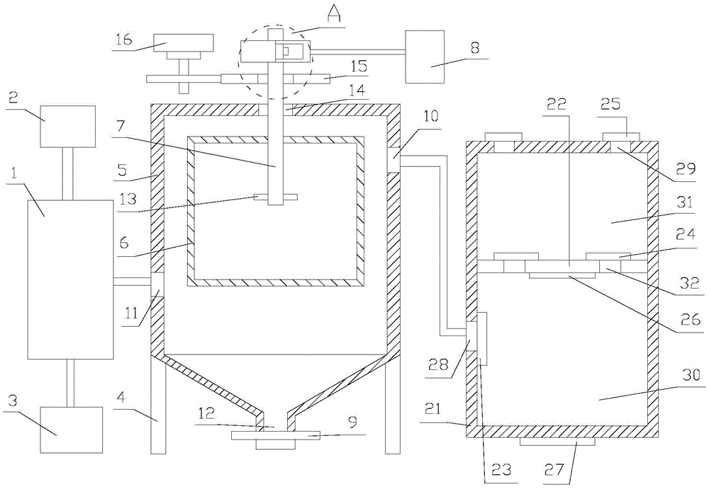
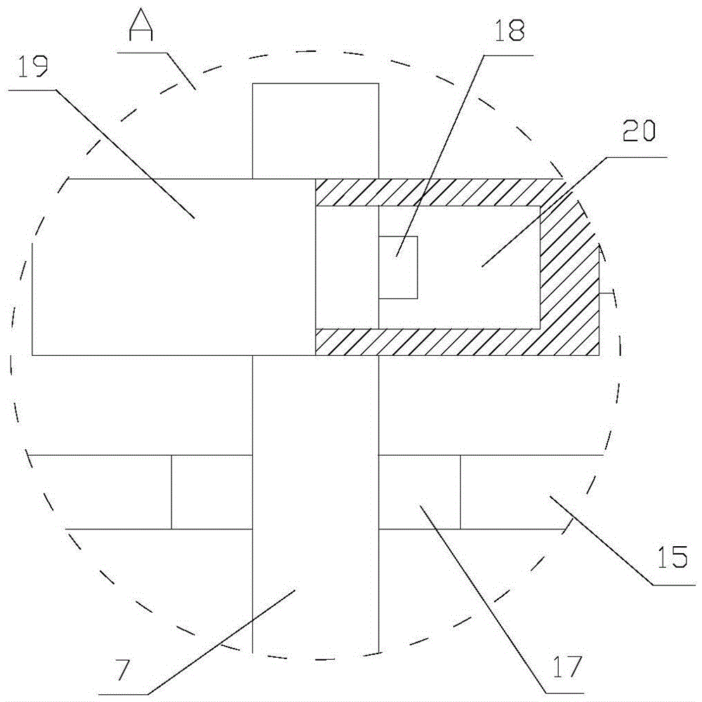
[0026] refer to figure 1 , 2 :

[0027] The present invention proposes a regenerated tail gas processor for electronic waste, comprising a semi-dry adsorption tower 1, a lime slurry preparation system 2, an activated carbon injection system 3, a dust collector, a suction mechanism, a lime slurry preparation system 2, an activated carbon injection system 3 and The semi-dry adsorption tower 1 is connected; the lime slurry sprayed by the lime slurry preparation system 2 is sprayed into the semi-dry adsorption tower 1, and the high-temperature gas of the semi-dry adsorption tower 1 is fully mixed with the injected lime slurry in a reverse flow , react with lime slurry t...


PUM


Abstract

The invention discloses an electronic garbage regeneration tail gas treatment device. The device comprises a semi-dry adsorption tower, a lime slurry preparation system and an active carbon injection system. The lime slurry preparation system and the active carbon injection system are communicated with the semi-dry adsorption tower. The device comprises a deduster and a suction blower. The electronic garbage regeneration tail gas treatment device has a simple structure and good impurity removal effects.

Description

technical field [0001] The invention relates to the technical field of waste gas treatment, in particular to a regenerated tail gas processor for electronic waste. Background technique [0002] The flue gas produced by electronic waste incineration mainly includes: 1. Acid gases (HCl, HF, SOx, etc.), dust (particulate matter), heavy metals (Hg, Pb, Cr, etc.) and highly toxic organic pollutants (dioxins, furans, etc.) etc.); HCl and HF are mainly produced during the incineration process of chlorine-containing plastics, resins and other organic matter in garbage; SOx is mainly produced during the incineration process of sulfur compounds contained in garbage, of which SO 2 Mainly, under the catalysis of heavy metals, a small amount of SO will be generated 3 . 2. The dust is mainly composed of inorganic components in the incineration products, with a particle size range of ≤200μm, usually at the outlet of the waste heat boiler. 3. Heavy metals include Hg, Cd, Pb, As, etc., wh...

Claims


Application Information

Patent Timeline
IPC IPC(8): B01D50/00B01D53/80B01D53/50B01D53/68
CPCB01D53/502B01D53/68B01D53/80B01D2258/0291B01D2257/302B01D2257/2045B01D2257/2047B01D53/10B01D2251/604B01D2251/404B01D50/20
Inventor 操应胜
Owner 宁国市四方钢球模具设备有限公司
Why Eureka
Try Eureka