
Evaporator for performing plant bionic remediation on contaminated soil

A plant bionic and polluted soil technology, applied in the field of soil remediation, to achieve the effect of improving remediation efficiency, speed and effect, and not easy to damage

Inactive Publication Date: 2016-05-04
BEIJING E & E TECH
View PDF7 Cites 13 Cited by
  • Summary
  • Abstract
  • Description
  • Claims
  • Application Information

AI Technical Summary

Problems solved by technology

[0005] The main purpose of the present invention is to solve the problem of preparation of the evaporator in the plant bionic restoration device, to improve the soil bionic restoration device through production, preparation and use of the evaporator, and to speed up the efficiency of soil restoration

Method used

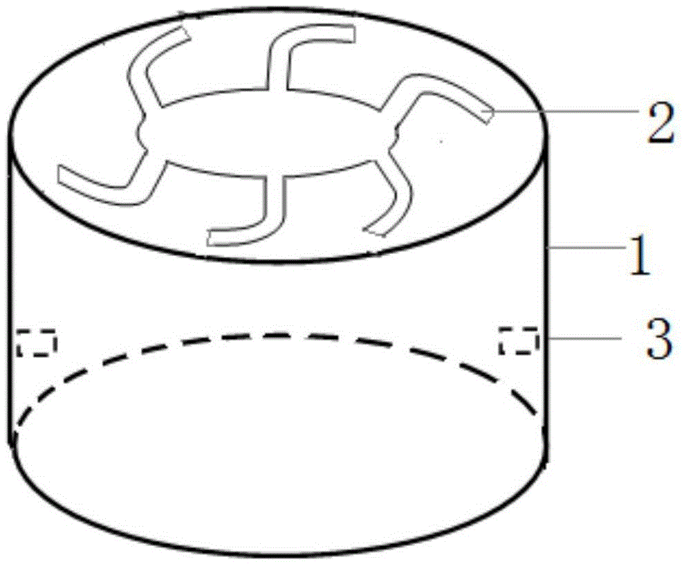
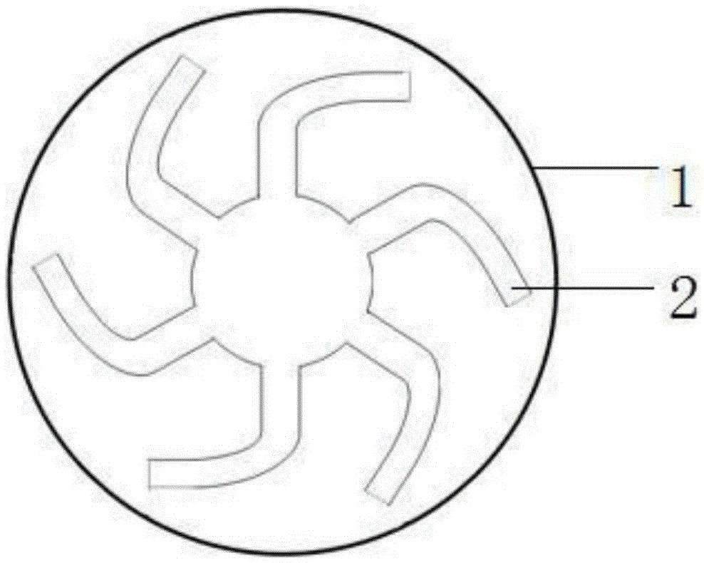

Image

  • Evaporator for performing plant bionic remediation on contaminated soil
  • Evaporator for performing plant bionic remediation on contaminated soil
  • Evaporator for performing plant bionic remediation on contaminated soil

Examples


Embodiment 1

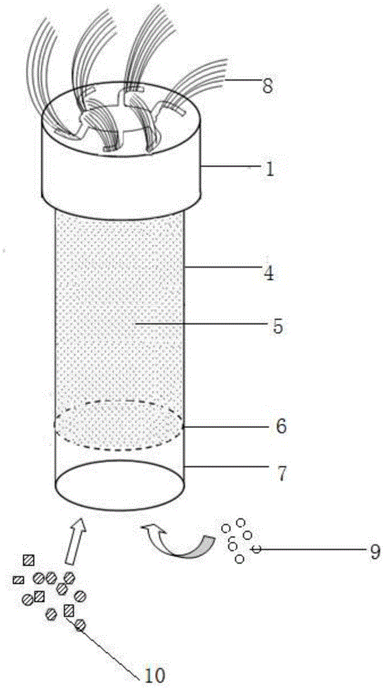
[0027] The structure of the in-situ self-sustaining repair device for contaminated soil based on plant bionics and the evaporator is as follows: image 3 Shown; The main part of the joint structure includes the repair device main body 4, filler repair agent 5, permeable membrane 6, accessories 7, evaporator main body 1 and evaporator fiber material 8. The main body of the repair device is a hollow pipe made of PVC material; the permeable membrane is attached to the bottom of the hollow pipe; the filler is tightly filled in the hollow pipe and compacted; the evaporator material is combined with the main body and fixed on the main pipe, and the evaporator fiber material penetrates Restorative filler.

[0028] Determination of transpiration rate of in-situ self-sustaining remediation device for contaminated soil based on plant bionics and comparison with plant transpiration rate. The transpiration rates of the glass fiber evaporator based on plant bionics of the present invention...

Embodiment 2

[0033] Remediation of industrially polluted soil by means of plant bionic remediation. The soil used in the test was taken from the polluted soil of an electroplating industrial park. According to the national soil environmental quality standard (GB15618-1995), the Cr and Ni in the polluted soil exceeded the natural background values ​​by 28.4 times and 3.1 times respectively. Utilize the plant bionic restoration technology of the present invention's combined structure to carry out on-the-spot restoration of industrially polluted soil, the fiber material of the evaporator is glass fiber, as shown in Table 2: after 1 month, the Cr reduction rate in the soil is 27%, and the Ni reduction rate is 24%. %; After 2 months, the Cr reduction rate in the soil was 41%, and the Ni reduction rate was 37%.

[0034] Table 2 Biomimetic remediation effect of contaminated soil

[0035]

[0036] From the data in Table 2, it can be seen that the plant bionic remediation technology has a good ...


PUM


Abstract

The invention discloses an evaporator for performing plant bionic remediation on contaminated soil and belongs to the technical field of soil remediation. The evaporator comprises an evaporator body and evaporator fiber materials. The evaporator body is of a cavity structure, an opening is formed in the lower end of the evaporator, a through hole is formed in the center of an upper end cover, multiple arc-shaped through holes are uniformly formed around the through hole in the center, and each arc-shaped through hole communicates or does not communicate with the through hole in the center. Pipe clamps are mounted on the inner side wall of the cavity of the evaporator body. The evaporator fiber materials penetrate through the arc-shaped through holes and are uniformly distributed along the arc-shaped structures of the arc-shaped through holes. The evaporator is used by being combined with a plant bionic device, and the lower ends of the evaporator fiber materials make contact with a filler remediation agent in a plant bionic remediation device body. The transfer of soil moisture and soil contaminants is improved through the evaporator, so that the rate of the plant bionic remediation is increased and effects of the plant bionic remediation are improved.

Description

technical field [0001] The invention relates to a preparation method of an evaporator for plant bionic restoration of polluted soil, and belongs to the field of soil restoration. Background technique [0002] Soil is the material basis for human survival, an indispensable and non-renewable natural resource for human beings, and an important part of the human environment. In recent years, with the rapid development of my country's industrial and agricultural production, township enterprises and rural urbanization, the problem of soil environmental pollution has become more and more serious. Relevant data show that the contaminated soil has reached more than 60 million hectares. Soil pollution is extremely harmful to human beings. It not only directly leads to the reduction of food production, but also affects human health through the food chain. In addition, pollutants in the soil cause adverse stress and harm to the human living environment through groundwater and the trans...

Claims


Application Information

Patent Timeline
IPC IPC(8): B09C1/00
CPCB09C1/00
Inventor 韩君徐愿坚周建强赵明阳吕学欠杨立鹏陈卫文高涛周敏
Owner BEIJING E & E TECH
Learn More