A polycrystalline ingot furnace with carrier gas heating device
A technology of heating device and polycrystalline ingot, which is applied in the direction of polycrystalline material growth, crystal growth, single crystal growth, etc., can solve the problems affecting the conversion efficiency of solar cells, achieve the suppression of impurity nucleation and impurity nuclei growth, and promote volatilization , conducive to the effect of uniform distribution
- Summary
- Abstract
- Description
- Claims
- Application Information
AI Technical Summary
Problems solved by technology
Method used
Image
Examples
Embodiment approach 1
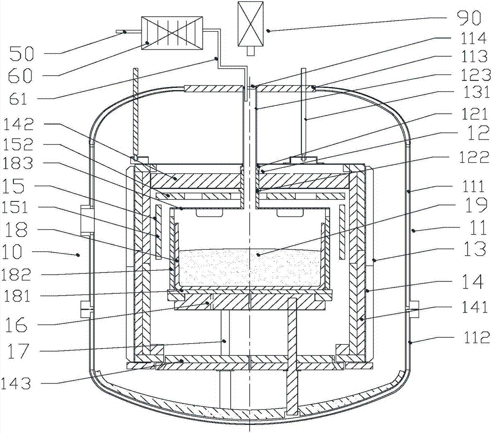
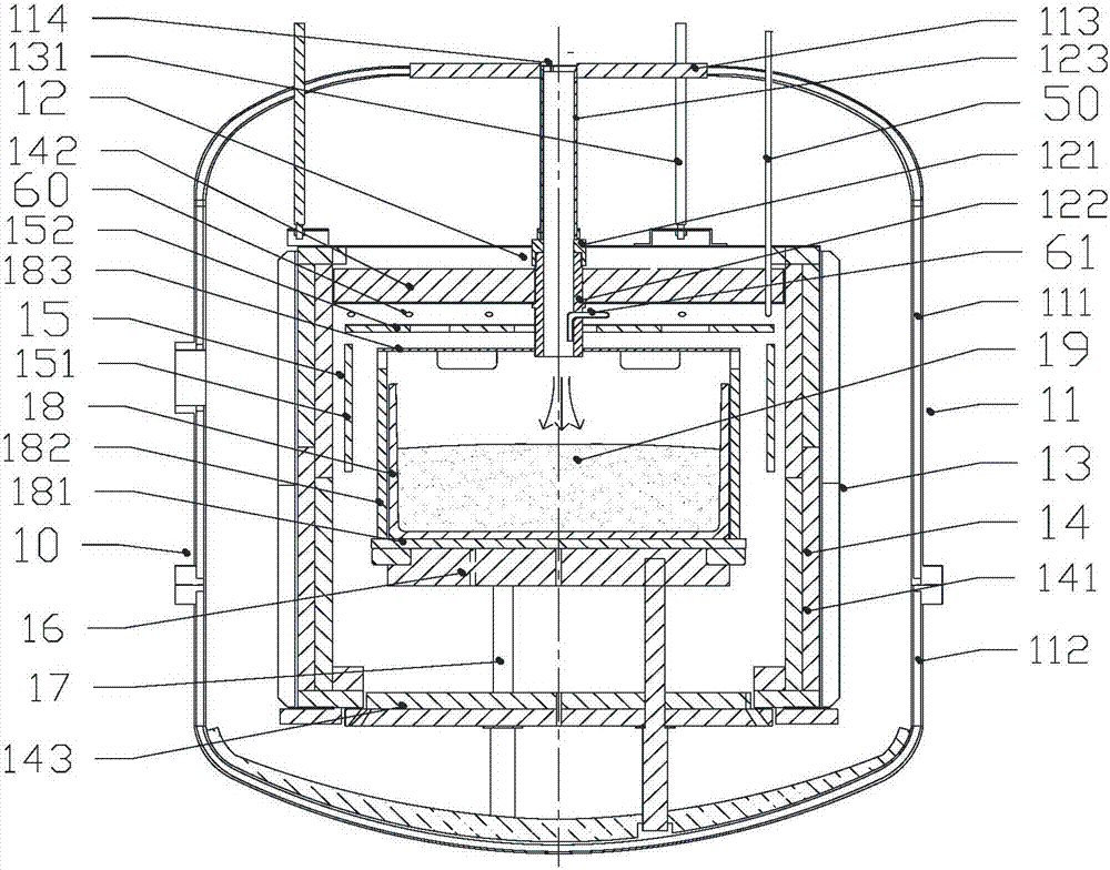
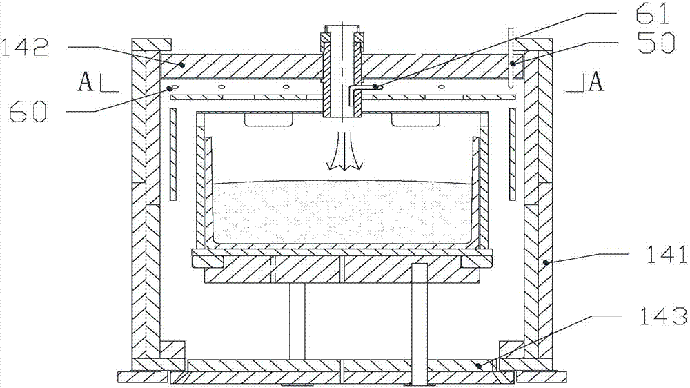
[0088] A kind of polycrystalline ingot casting furnace with carrier gas heating device of the present invention, as figure 1 , figure 2 As shown, the polycrystalline ingot furnace includes an ingot furnace body 10 and a heating device 60 for heating the carrier gas. The heating device 60 communicates with the ingot furnace body 10 for transporting the heated hot carrier gas to Inside the ingot casting furnace, the silicon material 19 in the crucible is blown, and the carrier gas carries the impurities volatilized in the silicon material 19 to the outside of the furnace to improve the purity and quality of the crystal.
[0089] The ingot furnace body 10 includes a furnace body 11, a cage frame 13, a lifting screw 131, a heat insulation cage 14, a heater 15, a heat exchange platform 16, a graphite column 17, a graphite tube 123, a drainage device 12, an infrared detector 90 and copper electrodes (not shown in the figure). The furnace body 11 includes an upper furnace body 111...
Embodiment approach 2
[0094] The difference between Embodiment 2 and Embodiment 1 is only that: a flow guiding device 20 is arranged in the polycrystalline ingot casting furnace, such as Figure 5 , Image 6 As shown, the flow guiding device 20 is used to divide the carrier gas into multiple beams of outgoing carrier gas flows, and the outgoing carrier gas flows are blown obliquely to different regions of the surface of the liquid silicon, forming carrier gas stress distributed around the center of the liquid silicon, and the carrier gas stress drives the liquid silicon. The silicon flows and forms a rotating flow field for circumferential flow in the liquid silicon. The air guide device 20 is provided with an air inlet 213 through which the carrier gas flows. The heating device 60 adopts the above-mentioned air heater, and the output end of the air heater communicates with the air inlet 213 of the flow guiding device 20 through the connecting pipe 61 (not shown in the figure), and the input end c...
Embodiment approach 3
[0103] The difference between Embodiment 3 and Embodiment 1 is only that: the polycrystalline ingot furnace has a built-in guide device 30, such as Figure 14 , Figure 15 As shown, the lower end of the drainage tube 122 of the drainage device 30 and the drainage device 12 is axially fixed. The deflector 30 is used to divide the carrier gas into multiple streams of outgoing carrier gas streams, and the outgoing carrier gas streams are blown obliquely to different areas of the surface of the liquid silicon, forming carrier gas stress distributed circumferentially around the center of the liquid silicon, and the carrier gas stress The liquid silicon is driven to flow, and a rotating flow field for circumferential flow is formed in the liquid silicon. The air guide device 30 is provided with an air inlet 33 through which the carrier gas flows. The heating device 60 adopts the above-mentioned heating tube arranged in the heat insulation cage, and the output end of the heating tu...
PUM
 Abstract
Description
Claims
Application Information
 - R&D
- Intellectual Property
- Life Sciences
- Materials
- Tech Scout
- Unparalleled Data Quality
- Higher Quality Content
- 60% Fewer Hallucinations
Browse by: Latest US Patents, China's latest patents, Technical Efficacy Thesaurus, Application Domain, Technology Topic, Popular Technical Reports.
© 2025 PatSnap. All rights reserved.Legal|Privacy policy|Modern Slavery Act Transparency Statement|Sitemap|About US| Contact US: help@patsnap.com


