
Centrifugal PCB plate automatic drying device

A technology of PCB board and drying device, which is applied in drying, drying machine, heating device and other directions, can solve the problem of high energy consumption of drying equipment, and achieve the effects of saving energy consumption, reducing production cost and simple device structure.

Active Publication Date: 2016-05-04
SUZHOU WUTONG ELECTRONICS CO LTD
View PDF8 Cites 5 Cited by
  • Summary
  • Abstract
  • Description
  • Claims
  • Application Information

AI Technical Summary

Problems solved by technology

[0003] The technical problem to be solved by the present invention is to provide a centrifugal automatic drying device for PCB boards to solve the problem of high energy consumption of existing drying equipment

Method used


Image

  • Centrifugal PCB plate automatic drying device
  • Centrifugal PCB plate automatic drying device

Examples


Embodiment Construction

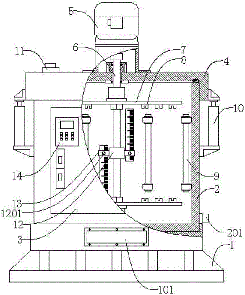
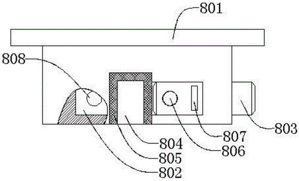
[0031] Such as figure 1 , figure 2 As shown, a centrifugal type PCB board automatic drying device includes a base 1, a drying barrel 2, a front door 3, a cover plate 4, a motor 5, a main shaft 6, a wheel 7 arranged symmetrically along the main shaft 6, and a limit Seat 8, heating pipe 9, cylinder 10, temperature sensor 11, sliding seat 12, scale 13, controller 14, the drying barrel 2 is located on the top of the base 1, and the drying barrel 2 is connected to the base 1 by threads , the front door 3 is located on the outer wall of the drying barrel 2, the front door 3 is hinged to the drying barrel 2, the cover plate 4 is located on the top of the drying barrel 2, and the cover plate 4 is connected to the drying barrel 2 Buckle connected, the motor 5 is located at the top of the cover plate 4, the motor 5 is threadedly connected with the cover plate 4, the main shaft 6 is located at the lower end of the motor 5 and runs through the cover plate 4, the said main shaft 6 and th...


PUM


Abstract

The invention discloses a centrifugal PCB plate automatic drying device which comprises a base, a drying barrel, a front door, a cover plate, a motor, a main shaft, wheel plates symmetrically arranged along the main shaft, limiting seats, heating tubes, air cylinders, a temperature sensor, a sliding seat, scaleplates and a controller. When in operation, the front door is manually opened, PCB plates to be processed are placed in the limiting seats, the front door is closed, and the controller controls the motor to drive the wheel plates to rotate at high speed through the main shaft, so that the PCB plates are driven to rotate at high speed, moisture attached in the surface and holes of the PCB plates are spin-dried, and wastewater is discharged through a water discharging connector; meanwhile, the heating tubes work until the temperature reaches the preset temperature of the temperature sensor, so that the temperature in the drying barrel keeps constant; the intervals of the wheel plates can be adjusted through cooperative use of the sliding seat and the scaleplates, so that the PCB plates with different height sizes can be adapted. The device is simple in structure, moisture in the surface and holes of the PCB plates are removed by adopting the high-speed centrifugal dewatering principle, energy consumption is greatly saved, and the production cost is reduced.

Description

technical field [0001] The invention relates to a drying device, in particular to a centrifugal automatic drying device for PCB boards. Background technique [0002] PCB (Printed Circuit Board), the Chinese name is a printed circuit board, also known as a printed circuit board, is an important electronic component, a support for electronic components, and a carrier for the electrical connection of electronic components. Double-sided, multi-layer and flexible, and still maintain their own development trends. Due to the continuous development towards high precision, high density and high reliability, the continuous reduction in size, cost reduction and performance improvement will make printed boards in the future In the development project of electronic equipment, it still maintains a strong vitality. The PCB board needs to be dried during the board making process. The existing drying equipment uses an air knife to blow high-pressure and high-temperature gas to the PCB board...

Claims


Application Information

Patent Timeline
Patent Type & Authority Applications(China)
IPC IPC(8): F26B5/08F26B11/16F26B23/06
CPCF26B5/08F26B11/16F26B23/06F26B2210/14
Inventor 张斯磊
Owner SUZHOU WUTONG ELECTRONICS CO LTD
Learn More