Self-adaptive double-light-comb spectrum system

A spectral system and dual optical comb technology, applied in the field of photoelectric detection, can solve the problems of compensation signal loss, limited photoelectric noise, beat frequency signal loss, etc., to achieve reduced bandwidth and complexity, flexible selection methods, and high measurement accuracy Effect

Active Publication Date: 2016-05-04
UNIV OF SHANGHAI FOR SCI & TECH
View PDF6 Cites 16 Cited by
  • Summary
  • Abstract
  • Description
  • Claims
  • Application Information

AI Technical Summary

Problems solved by technology

However, since the two pulsed lasers are completely free, random, and uncorrelated, this will lead to a large long-term drift of the beat frequency signals of the pulsed laser and the continuous laser, even exceeding the bandwidth of the filter. , leading to the loss of compensation signal during signal processing, which in turn causes the failure of the adaptive dual-comb spectroscopy system
[0005] To sum up, the traditional dual-comb spectrum light source is a compact and precisely locked pulsed laser, but limited by the photoelectric noise introduced in the measurement and control process, it is impossible to obtain a spectral measurement accuracy that meets the Doppler limit; and the current The light source of some adaptive dual-comb spectroscopy systems is completely free, random, and unrelated. Although this method avoids noise in the measurement and control process, there is a major hidden danger of beat frequency signal loss, which affects the long-term operation of the system. stability, reliability

Method used


Image

  • Self-adaptive double-light-comb spectrum system
  • Self-adaptive double-light-comb spectrum system
  • Self-adaptive double-light-comb spectrum system

Examples


Embodiment Construction

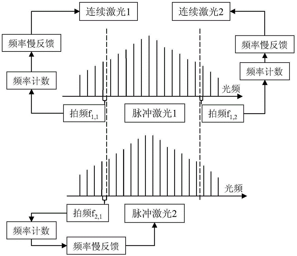
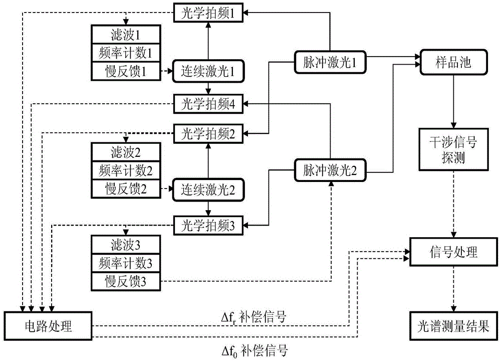
[0017] Such as figure 1 The schematic diagram of the self-adaptive dual-comb spectroscopy system is shown, including pulsed laser 1, pulsed laser 2, continuous laser 1, continuous laser 2, and three beat frequency detection modules, three frequency counting modules and three frequency slow feedback modules.

[0018] The beat frequency signals of pulsed laser 1 and continuous laser 1 detected by the first beat frequency detection module are f 1.1 , through the first frequency counting module, measure the specific value of the beat frequency signal, and then set the upper limit and lower limit of the drift value of the frequency according to the bandwidth of the selected filter, when the free drift range of the beat frequency signal exceeds the set When the frequency upper limit or lower limit is set, the first frequency slow feedback module starts to work. By controlling the pumping current, operating temperature, and output optical frequency of the continuous laser 1, the beat...


PUM


Abstract

The invention relates to a self-adaptive double-light-comb spectrum system. The system includes two pulse lasers, one or two continuous lasers, and optical beat frequency modules which are used for detecting beat frequency signals generated from any combination of the pulse lasers and the continuous lasers. One path of the beat frequency signals are directly sent to a circuit processing module, and the other path passes through filters for smoothing and is sent to frequency counting. The counted number is compared with a set value. A control signal is output to a frequency slow feedback module. Working parameters of the continuous lasers are adjusted to enable the obtained beat frequency signals to work in a defined range. The circuit processing module carries out circuit treatment including smoothing, frequency mixing, and frequency doubling on the beat frequency signals in order to extract a compensating signal representing double-light-comb repetition frequency and carrier envelope phase jitter. Frequency counting and slow feedback are adopted to control drift of the beat frequency signals of pulsed light and continuous light in self-adaptive double-light-comb spectrum measurement to be in a certain frequency range. It is ensured that the beat frequency signals can stably exist for a long time, thereby improving stability of the self-adaptive double-light-comb spectrum system.

Description

technical field [0001] The invention relates to a photoelectric detection technology, in particular to an adaptive double-comb spectrum system. Background technique [0002] As a frontier topic in the field of scientific research in recent years, dual-comb spectroscopy technology can greatly improve the accuracy of spectral detection. Compared with the traditional technology, the dual optical comb spectral detection technology has two improvements. One is to use an optical comb to replace the traditional light source. As a standard, the position of the frequency spectral line is more stable, the line width is narrower, and the accuracy is higher; Optical combs with slightly different frequencies are measured at the same time. One is used as a reference comb and the other is used as an excitation comb, which is similar to the main scale and auxiliary scale of a vernier caliper. Through frequency misalignment and beat frequency detection, the accuracy of frequency measurement ...

Claims


Application Information

Patent Timeline
Patent Type & Authority Applications(China)
IPC IPC(8): G01N21/27
CPCG01N21/27
Inventor 杨康文沈旭玲郝强曾和平
Owner UNIV OF SHANGHAI FOR SCI & TECH
Why Eureka
Try Eureka