
SRAM type FPGA test method based on irradiation test environment simulation

A test method and test environment technology, applied in the aerospace field, can solve problems such as limited test time, inconsistent irradiation test environment, and high test difficulty, so as to reduce design costs and test costs, verify system reliability, and process safety. The effect of pollution

Inactive Publication Date: 2016-05-04
INST OF ELECTRONICS CHINESE ACAD OF SCI
View PDF4 Cites 9 Cited by
  • Summary
  • Abstract
  • Description
  • Claims
  • Application Information

AI Technical Summary

Problems solved by technology

[0009] (1) After the ground irradiation test, the device under test cannot be used due to damage, the cost is high, the test is difficult, and the test parameters are troublesome to adjust, which may cause radiation pollution and has a high risk
Moreover, it is difficult to apply for domestic irradiation testing machines, and the testing time is limited;
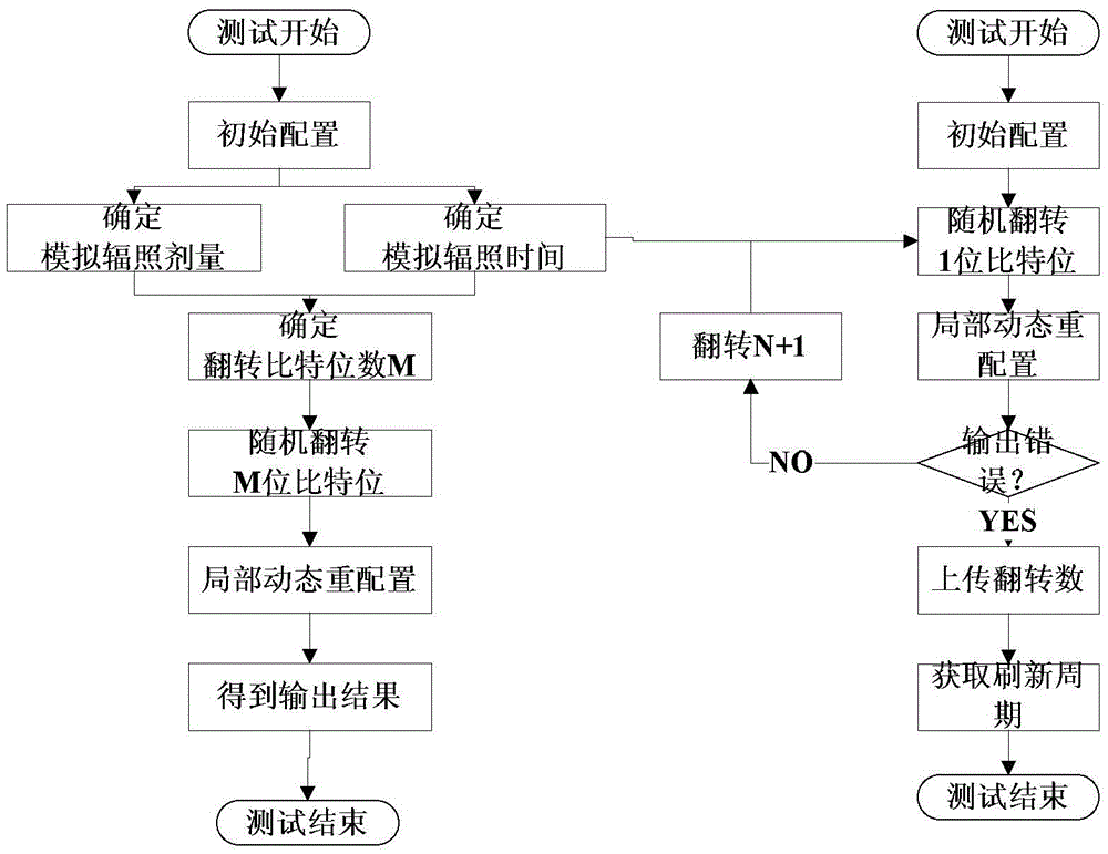
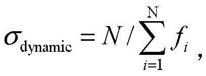
[0010] (2) Patent CN102540062A simulates the irradiation dose and irradiation time, but it cannot obtain the relationship curve between the dynamic flip section of the circuit design and the parameters such as the LET value of the incident particles, the fluence rate Flux, etc. like the irradiation test, and the reference value of the test results limited
Moreover, after the invention calculates the number M of bit flips, all faults are injected into the circuit design through only one partial reconstruction, which is inconsistent with the real irradiation test environment;
[0011] (3) The patent CN102540062A requires an additional method of unit random flipping to calculate the refresh cycle of the circuit design, and the operation is more complicated;
[0012] (4) Patent CN102540062A only considers single-bit upset (SBU) fault type, but as the feature size of the device decreases, a single particle incident may cause charge collection in multiple adjacent PN junctions, causing multi-bit upset (MBU) );
[0013] (5) Patent CN102540062A needs to use an additional method, which is specially used to obtain the refresh cycle, and the operation is relatively complicated and the efficiency is low

Method used


Image

  • SRAM type FPGA test method based on irradiation test environment simulation
  • SRAM type FPGA test method based on irradiation test environment simulation
  • SRAM type FPGA test method based on irradiation test environment simulation

Examples


Embodiment approach

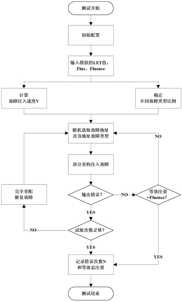
[0031] According to an embodiment of the present invention, the SRAM type FPGA test method based on the simulation of the irradiation test environment includes:

[0032] S1, input the test parameters of the simulated irradiation test;

[0033] S2, according to the test parameters, calculate the fault injection speed V and the time interval t between two adjacent injection faults, and determine the proportion of different fault types;

[0034] S3, according to the proportion of each fault type, randomly select the fault address and the fault type of the address, select the random function with the current system time as the seed, determine the fault address and fault type to be injected, read the corresponding configuration frame and complete the corresponding bit Bit flipping, adding corresponding configuration commands to generate code stream files with fault frame data, performing partial reconstruction to complete fault injection;


PUM


Abstract

The invention provides an SRAM type FPGA test method based on irradiation test environment simulation. Fault injection is performed on a circuit realized by adoption of an SRAM type FPGA, by continuous injection of single event upset faults of random addresses and random types into the circuit, influence of parameters of an incident particle LET value, fluence rate Flux and fluence Fluence on the circuit in a ground irradiation test is simulated, and effectiveness of circuit reinforcing design is quantitatively evaluated. The SRAM type FPGA test method provided by the invention can obtain a characteristic curve of changes of a dynamic upset section of the circuit with the LET value, thereby estimating an in-orbit failure rate.

Description

technical field [0001] The invention belongs to the field of aerospace, and relates to a SRAM type FPGA test method based on radiation test environment simulation. Background technique [0002] SRAM (Static Random Access Memory) FPGA (Field Programmable Gate Arrays) has received more and more attention and applications in the aerospace field due to its advantages of reprogrammable, short development cycle, and high integration. However, in the space environment, the single event effect (Single Event Effect, SEE) especially the single event upset (Single Event Upset, SEU) caused by the bombardment of high-energy particles seriously affects the reliability of aerospace devices. Therefore, the user design must be evaluated for reliability before application. [0003] For the design of SRAM FPGA, there are two commonly used reliability evaluation methods: ground radiation test and fault injection. The former uses accelerators to generate heavy ions, protons and neutrons with d...

Claims


Application Information

Patent Timeline
IPC IPC(8): G01R31/3185
CPCG01R31/318519
Inventor 杨海钢李林蔡刚贾海涛李悦卢凌云徐宇
Owner INST OF ELECTRONICS CHINESE ACAD OF SCI
Learn More