Usage method of harmonic radar with positioning function

A harmonic and radar technology, which is applied in the field of near-field nonlinear target harmonic radar detection, can solve the problems of inability to identify random electromagnetic interference signals and pulse noise interference signals, the signal system does not have processing gain, and the detection sensitivity is not enough.

Inactive Publication Date: 2016-05-04
NO 50 RES INST OF CHINA ELECTRONICS TECH GRP
View PDF8 Cites 10 Cited by
  • Summary
  • Abstract
  • Description
  • Claims
  • Application Information

AI Technical Summary

Problems solved by technology

[0004] 1. The detection sensitivity is not enough. Specifically, the traditional harmonic radar relies on reducing the channel bandwidth and increasing the time accumulation width to achieve the goal of improving its detection sensitivity. The signal system itself does not have processing gain, and it is difficult to further improve the system sensitivity.
[0005] 2. The anti-electromagnetic interference performance is poor. Specifically, due to its narrow-band receiving characteristics, the radar itself cannot distinguish the echo characteristics of various interference signals and target signals. While improving the detection sensitivity, its anti-electromagnetic interference performance will also be get worse
Using the frequency selection method can avoid the influence of partially deterministic electromagnetic interference signals, but it is impossible to identify random electromagnetic interference signals and impulse noise interference signals in this way
[0006] 3. There is no target positioning and resolution capability, and further expansion of the application field is limited

Method used


Image

  • Usage method of harmonic radar with positioning function
  • Usage method of harmonic radar with positioning function
  • Usage method of harmonic radar with positioning function

Examples


Embodiment Construction

[0033] The present invention will be described in detail below in conjunction with specific embodiments. The following examples will help those skilled in the art to further understand the present invention, but do not limit the present invention in any form. It should be noted that those skilled in the art can make several modifications and improvements without departing from the concept of the present invention. These all belong to the protection scope of the present invention.

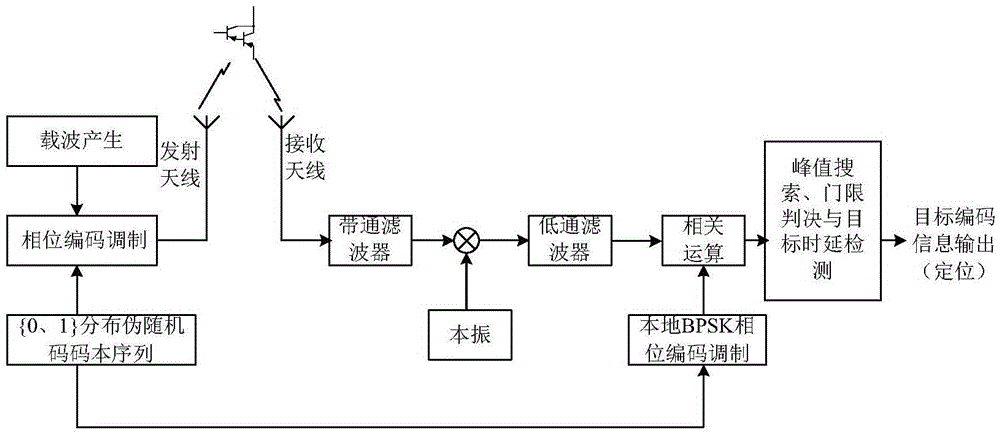
[0034] In this embodiment, the method for using the harmonic radar with positioning function provided by the present invention includes the following steps:

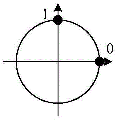
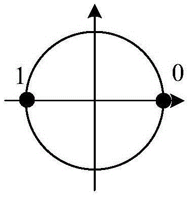
[0035] Step S1: Perform unbalanced quadrature phase encoding modulation on the pseudo-random codebook sequence used, and then modulate the phase of the signal generated by the carrier to generate a harmonic radar transmission signal;

[0036] Step S2: performing band-pass filtering, harmonic frequency de-carrier mixing and low-pass filtering...


PUM


Abstract

The invention provides a usage method of a harmonic radar with a positioning function. The method comprises the steps of: carrying out nonequilibrium quadrature phase code modulation on an adopted pseudo random codebook sequence, and further modulating the phase of a carrier generation signal and generating a harmonic radar emission signal; carrying out band-pass filtering, carrier mixed frequency removing from harmonic frequency, and low-pass filtering on a received non-linear target reradiation harmonic frequency signal, and obtaining a harmonic baseband signal; carrying out two-phase coded modulation on the adopted pseudo random codebook sequence, and generating a local two-phase coded baseband signal; carrying out cross correlation operation on the harmonic baseband signal and the local two-phase coded baseband signal, carrying out peak value searching and threshold decision on a calculation result, carrying out detection on corresponding target time delay information, calculating the corresponding distance position information according to the target time delay information, further generating detection information, and coding and outputting the detection information. The usage method of the harmonic radar with the positioning function has the advantages that the detection sensitivity is high, the interference resistance is high, and high-precision positioning is realized.

Description

technical field [0001] The invention relates to a near-field nonlinear target harmonic radar detection technology, in particular to a method for using a harmonic radar with a positioning function using a broadband unbalanced quadrature pseudo-randomly coded phase modulation signal and digital pulse compression. Background technique [0002] The existing harmonic radar technology mainly adopts a narrowband signal system, which transmits one or more single-frequency signals during operation. After the signal is irradiated to a nonlinear target, it can radiate a new harmonic or a combined harmonic signal, which can be detected by narrowband detection. , The method of time integration detects the size of the re-radiated signal energy at the receiving end to realize the detection of nonlinear targets. The radar working principle of this system is clear and easy to implement. A flexible compromise can be achieved between detection time and detection sensitivity. Applicability is b...

Claims


Application Information

Patent Timeline
Patent Type & Authority Applications(China)
IPC IPC(8): G01S13/04G01S13/06
CPCG01S13/04G01S13/06
Inventor 张文济汪海勇吴美武石智友唐云峰叶联源曹照清童芸
Owner NO 50 RES INST OF CHINA ELECTRONICS TECH GRP
Why Eureka
Try Eureka