
High-voltage DC relay and assembly method thereof

A high-voltage direct current and relay technology, applied in the direction of relays, electromagnetic relays, detailed information of electromagnetic relays, etc., can solve problems such as difficulty in ensuring the accuracy of push rod components, sticking or burning of dynamic and static contacts, and difficulty in realizing automatic assembly, etc., to achieve Easy automatic assembly, easy guarantee of dimensional accuracy, and simple structure

Active Publication Date: 2016-05-04
XIAMEN HONGFA ELECTRIC POWER CONTROLS
View PDF4 Cites 13 Cited by
  • Summary
  • Abstract
  • Description
  • Claims
  • Application Information

AI Technical Summary

Problems solved by technology

A kind of direct current relay of prior art, its push bar assembly is usually to adopt integral injection molding (as disclosed in patent publication number CN104412353A), this push bar assembly is that push bar and U-shaped basket are injection molded together, and push bar It is used to connect the moving iron core, and the U-shaped basket is used to adapt to the moving spring part. Since the push rod and the U-shaped basket are integrally injection molded, it is difficult to guarantee the accuracy of the push rod assembly, which makes injection molding difficult and inconvenient. Into the moving spring part, it is more difficult to realize automatic assembly
On the other hand, the existing high-voltage DC relays are likely to cause sticking or burning of the moving and static contacts due to the generation of arcs when a large current is connected.

Method used


Image

  • High-voltage DC relay and assembly method thereof
  • High-voltage DC relay and assembly method thereof
  • High-voltage DC relay and assembly method thereof

Examples


Embodiment 1

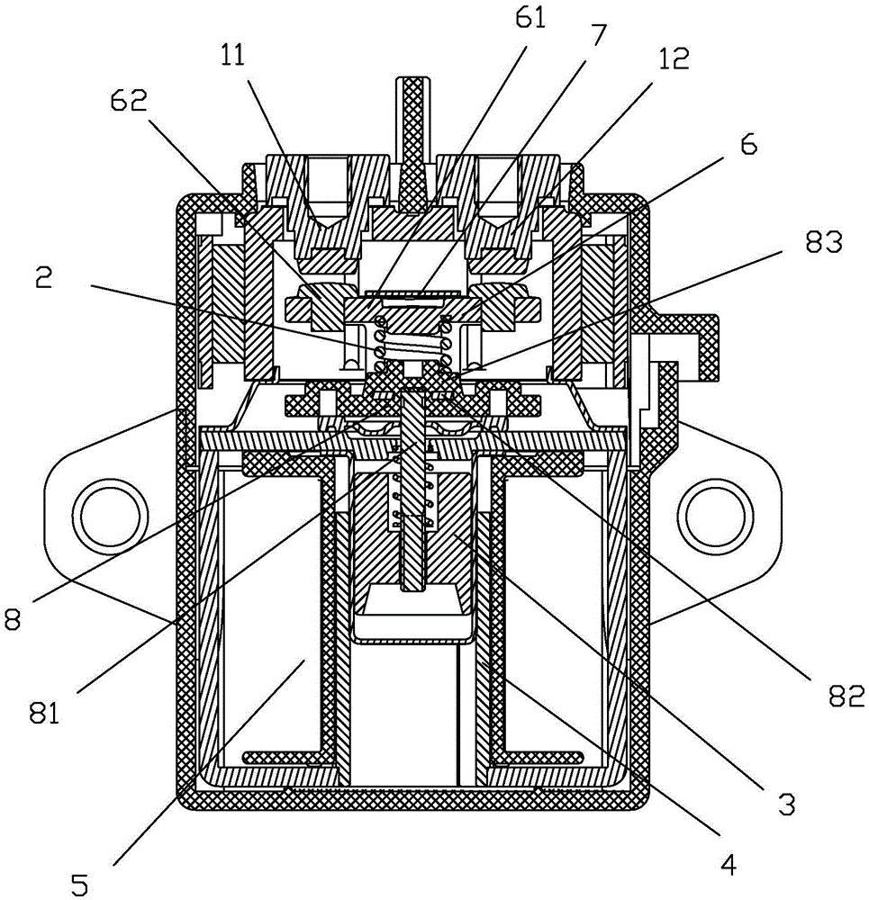
[0051] see Figure 1 to Figure 9 As shown, a high-voltage DC relay of the present invention includes two static contacts 11, 12, a moving assembly, a moving iron core 3, a yoke 4, a coil 5 and other components.

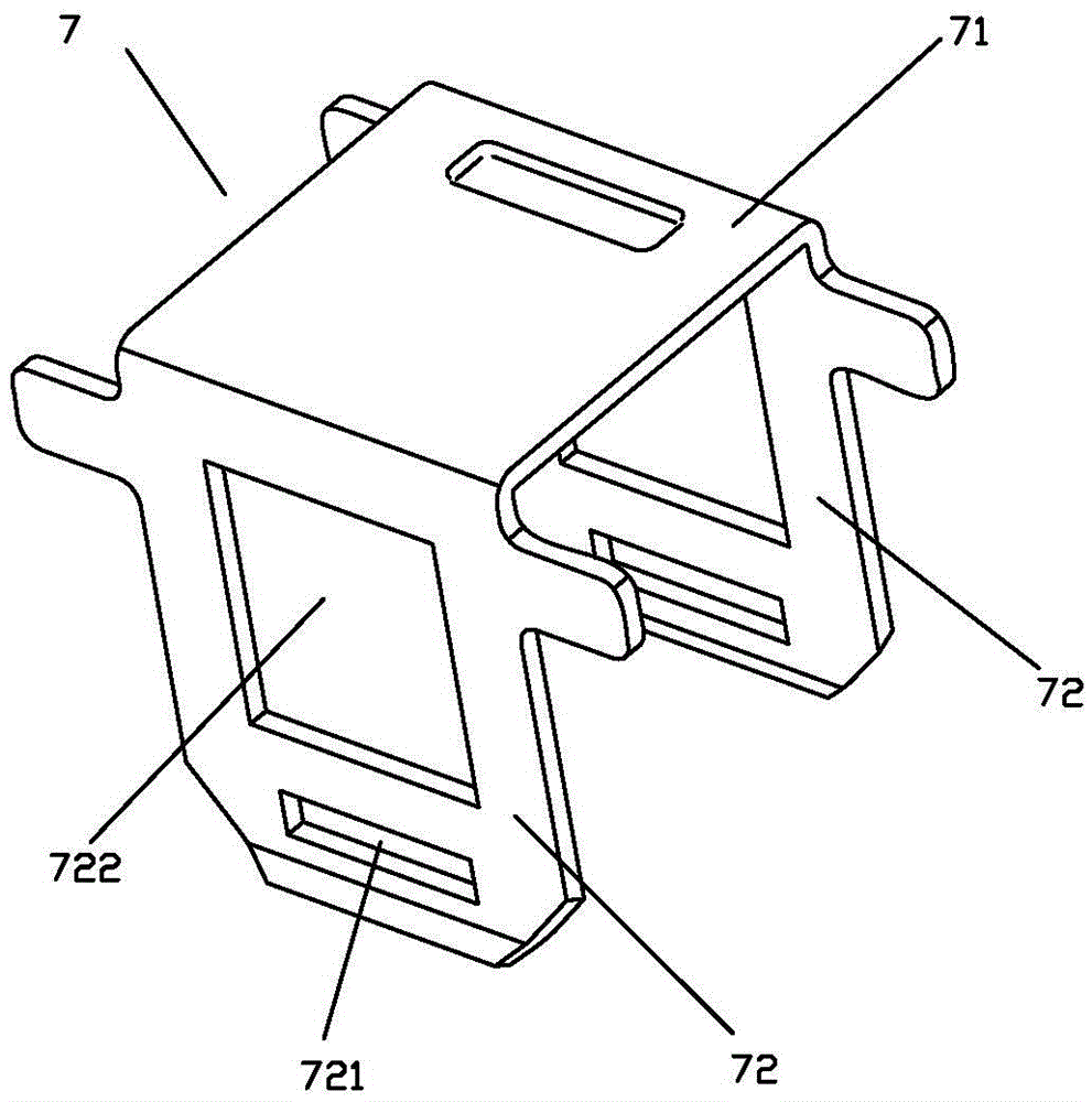
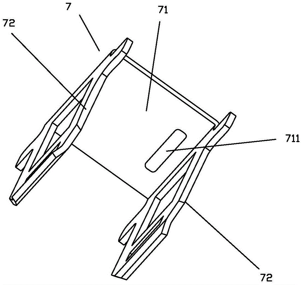
[0052] The moving assembly includes a moving spring part 6, a main spring 2 and a push rod assembly; the moving spring part 6 is made of a moving reed 61 and a moving contact 62 at both ends of the moving reed; the pushing rod assembly consists of a pushing rod The part 8 and the U-shaped basket 7 made of metal materials are composed of two independent parts. The fixed piece 82 and the push rod 81 fixed together by insulating plastic, the fixed piece 82 is also made of metal material, one end of the push rod 81 is connected with the fixed piece 82 through the insulating plastic, and the other end of the push rod 81 is connected with the moving iron core 3 When the moving contacts 62 at both ends of the moving reed 61 are in contact with the static contacts of the two...

Embodiment 2

[0071] see Figure 10 to Figure 11 As shown, a high-voltage direct current relay of the present invention is different from Embodiment 1 in that a second convex bud 712 is also provided on the inner side of the top 71 of the U-shaped basket 7, and the second convex bud 712 It is arranged on the other side corresponding to the width of the moving reed, and the height dimension of the second convex bud 712 is set to have a height difference from the height dimension of the first convex bud 711. In this embodiment, the height dimension of the second convex bud 712 is Greater than the height dimension of the first convex bud 711, so that when the contact is disconnected, the inner side of the top 71 of the U-shaped basket 7 is pressed against the movable reed 61, and the movable reed 61 moves to the other side of the width tilt.

[0072] The second convex bud 712 is formed by bending the corresponding position of the top 71 of the U-shaped basket or punching the bud by using a mo...

Embodiment 3

[0074] see Figure 12 to Figure 15 As shown, a kind of high-voltage direct current relay of the present invention is different from Embodiment 1 in that the first convex bud corresponding to the side of the width of the moving reed is not provided on the inner side of the top of the U-shaped basket, but on the inner side of the U-shaped basket. One side corresponding to the length of the movable reed is provided with a third protruding bud 713, and the third protruding bud 713 makes when the contact is disconnected, the third protruding bud 713 on the inner side of the top 71 of the U-shaped basket 7 is connected to the movable reed 61. As a result of the tension, the moving reed 61 is inclined to one side of the length (as Figure 14 , Figure 15 shown).

[0075] The third convex bud 713 is formed by bending the corresponding position of the top 71 of the U-shaped basket or punching the bud by using a mold.

[0076] A kind of high voltage direct current relay of the presen...


PUM


Abstract

The invention discloses a high-voltage DC relay and an assembly method thereof. The high-voltage DC relay comprises two fixed contacts and a movable assembly, wherein the movable assembly comprises a movable spring part, a main spring and a push rod assembly, the push rod assembly comprises two independent parts of a push rod part and an U-shaped basket, the push rod part comprises a fixed piece and a push rod which are fixed together by insulation plastic, the two ends of the fixed piece are respectively fixed with the bottom of the side part of the U-shaped basket after the main spring, the movable spring part and the U-shaped basket are sequentially arranged at the top of the push rod part, so that the main spring is elastically tightened between the bottom surface of the movable spring part and the insulation plastic of the push rod part, and a movable spring piece props against the inner side of the top of the U-shaped basket. By dividing the push rod assembly into two independent parts, the high-voltage DC relay has the characteristics of simplicity in structure, convenience in forming and easiness in ensuring size accuracy; meanwhile, the two parts are easy to assemble, and automatic assembly of parts which are mutually matched is easily achieved; and moreover, the bonding resistant ability also can be enhanced.

Description

technical field [0001] The invention relates to a DC relay, in particular to a high-voltage DC relay and an assembly method thereof. Background technique [0002] The relay is an electronic control device, which has a control system (also known as the input circuit) and a controlled system (also known as the output circuit), usually used in automatic control circuits, it actually uses a smaller current to control a larger An "automatic switch" of electric current. Therefore, it plays the role of automatic adjustment, safety protection, and conversion circuit in the circuit. [0003] The DC relay is one of the relays. Most of the existing DC relays adopt the scheme of moving reed direct action (also known as solenoid direct action). The contact part of the DC relay includes two static contacts and a The moving assembly, the moving assembly includes the moving spring part and the push rod assembly. The moving spring part is composed of the moving reed and the moving contacts...

Claims


Application Information

Patent Timeline
IPC IPC(8): H01H50/64H01H49/00
CPCH01H49/00H01H50/641H01H50/64H01H1/18H01H1/2008H01H1/50H01H50/20H01H50/546
Inventor 施生圣钟叔明
Owner XIAMEN HONGFA ELECTRIC POWER CONTROLS
Learn More