Vacuum system

A technology of vacuum system and vacuum pump, applied in the field of vacuum system, can solve the problem that the chamber cannot continue to work, and achieve the effect of improving the operating time and increasing the production capacity

Active Publication Date: 2016-05-04
WUHAN CHINA STAR OPTOELECTRONICS TECH CO LTD
View PDF3 Cites 15 Cited by
  • Summary
  • Abstract
  • Description
  • Claims
  • Application Information

AI Technical Summary

Problems solved by technology

[0003] The purpose of the present invention is to provide a vacuum system aimed at solving the problem that the corresponding chamber cannot continue to work due to abnormal shutdown of the vacuum pump

Method used


Image

  • Vacuum system
  • Vacuum system
  • Vacuum system

Examples


Embodiment 1

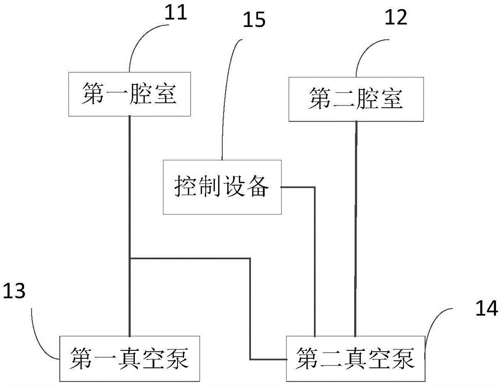
[0023] Such as figure 1 As shown, Embodiment 1 of the vacuum system of the present invention includes:

[0024] The first chamber 11, the second chamber 12, the first vacuum pump 13, the second vacuum pump 14 and the control device 15;

[0025] The first vacuum pump 13 is connected to the first chamber 11 for evacuating the first chamber 11 under normal operating conditions, and the second vacuum pump 14 is connected to the second chamber 12 for evacuating the second chamber under normal operating conditions. 12 vacuumize, the first chamber 11 is further connected with the second vacuum pump 14;

[0026] The control device 15 is used to use the second vacuum pump 14 to simultaneously evacuate the first chamber 11 and the second chamber 12 when the first vacuum pump 13 is abnormally shut down.

[0027] Under normal working conditions, the first chamber 11 maintains a communication state with the first vacuum pump 13, and is connected but not communicated with the second vacuu...

Embodiment 2

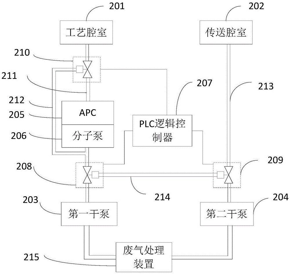
[0037] Such as image 3 As shown, the second embodiment of the vacuum system of the present invention is a dry etching vacuum system, including: a first chamber 201, a second chamber 202, a first vacuum pump 203, a second vacuum pump 204 and a control device 207, wherein the first The chamber 201 is a process chamber 201, the second chamber 202 is a transfer chamber 202, the first vacuum pump 203 is a first dry mechanical pump (dry pump for short) 203, and the second vacuum pump 204 is a second dry pump 204. The device 207 is a PLC logic controller 207 .

[0038] The process chamber 201 and the transfer chamber 202 are connected in series. During production, the raw materials are transported to the process chamber 201 through the transfer chamber 202 for processing, and the samples processed in the process chamber 201 are transferred out through the transfer chamber 202 . A first pipeline 211 is connected between the process chamber 201 and the first dry pump 203. The first p...


PUM


Abstract

The invention discloses a vacuum system, which comprises a first cavity, a second cavity, a first vacuum pump, a second vacuum pump and a control device, wherein the first vacuum pump is connected with the first cavity for carrying out vacuum pumping on the first cavity in a normal working state; the second vacuum pump is connected with the second cavity for carrying out vacuum pumping on the second cavity in a normal working state, and the first cavity is further connected with the second vacuum pump; and the control device is used for using the second vacuum pump to carry out vacuum pumping on the first cavity and the second cavity at the same time in a state in which the first pump vacuum stops abnormally. Through the above mode, the first cavity of the vacuum system does not stop as the first vacuum pump stops abnormally, during the repair process of the first vacuum pump, continuous production is carried out through operation of the second vacuum pump, the operation time of the system is improved, and the productivity is enhanced.

Description

technical field [0001] The invention relates to the field of vacuum technology, in particular to a vacuum system. Background technique [0002] The multi-chamber vacuum system is used in the field of semiconductor processing. Vacuum systems such as Dry Etcher, Chemical Vapor Deposition (CVD), and Physical Vapor Deposition (PVD) are used to process semiconductors. Processed materials are processed in a vacuum environment. In a multi-chamber vacuum system, an independent vacuum pump is usually used to evacuate a certain chamber. By continuously changing the volume of the suction cavity in the pump, the volume of the gas in the pumped chamber is continuously expanded to obtain the required vacuum. Environment, long-term operation will cause the vacuum pump to stop abnormally due to abnormal temperature or high back pressure, resulting in the corresponding chamber also stopping work, unable to carry out production, and the process of repairing the vacuum pump generally takes a ...

Claims


Application Information

Patent Timeline
Patent Type & Authority Applications(China)
IPC IPC(8): H01L21/67C23C14/56C23C16/54
CPCC23C14/56C23C16/54H01L21/67011
Inventor 蔡文
Owner WUHAN CHINA STAR OPTOELECTRONICS TECH CO LTD
Why Eureka
Try Eureka