Brushless wiper motor

A wiper and sensor technology, which is applied in the field of brushless wiper motors, can solve the problems of loud sliding contact between the brush and the commutator, unstable operation of the wiper motor, and restrictions on the miniaturization of the wiper motor, so as to achieve light weight, shortened size, Realize the effect of cost reduction

Inactive Publication Date: 2016-05-04
MITSUBA CORP
View PDF5 Cites 12 Cited by
  • Summary
  • Abstract
  • Description
  • Claims
  • Application Information

AI Technical Summary

Problems solved by technology

[0005] In such a wiper motor with brushes, the output of the wiper motor is limited due to the increase in the temperature of the brush, such as a decrease in the output of the wiper motor, which causes unstable operation of the wiper motor.
In addition, the sliding contact between the brush and the commutator is relatively loud, so it is necessary to have anti-noi

Method used


Image

  • Brushless wiper motor
  • Brushless wiper motor
  • Brushless wiper motor

Examples


Embodiment Construction

[0040] Hereinafter, a first embodiment of the present invention will be described in detail with reference to the drawings.

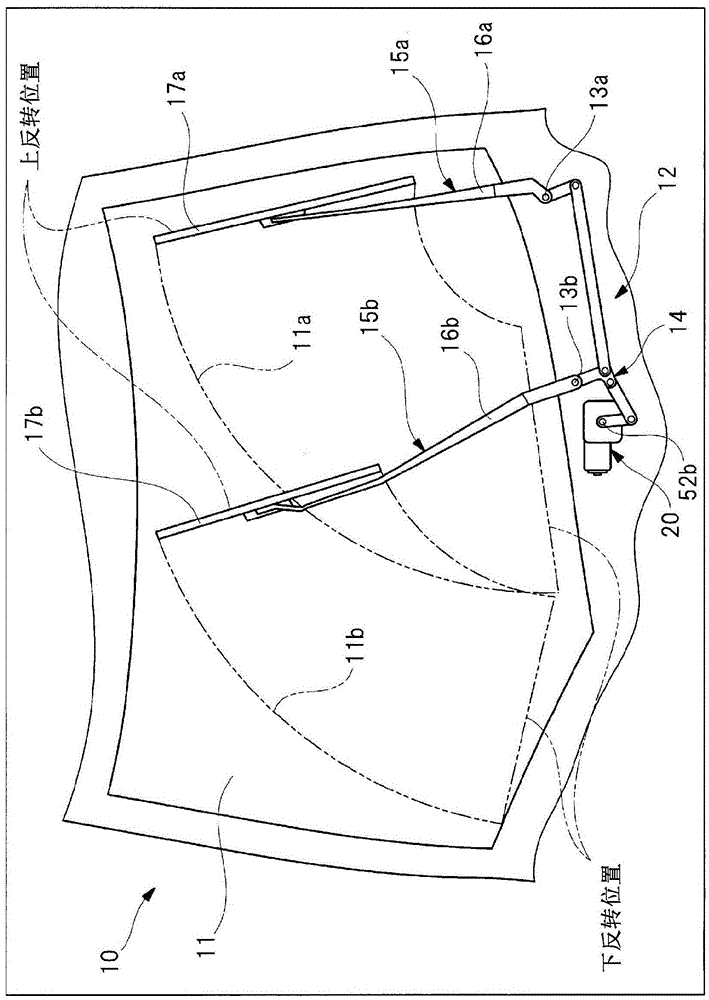
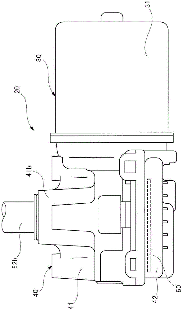
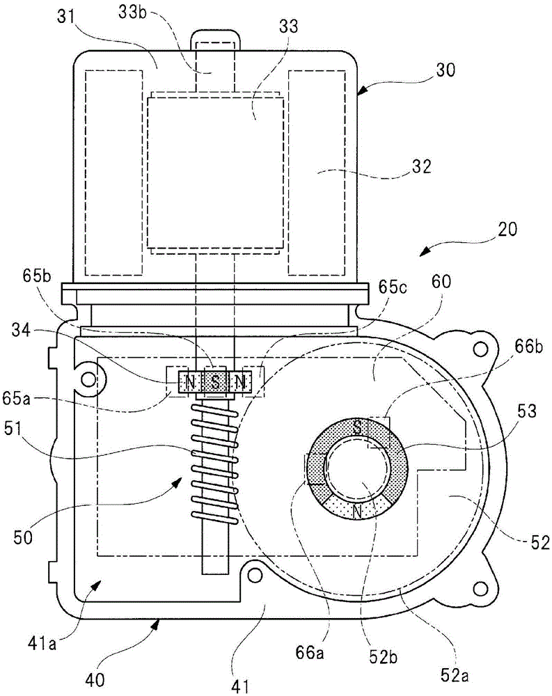
[0041] figure 1 To show a vehicle installation diagram of a wiper device having a wiper motor of the present invention, figure 2 to show figure 1 The appearance diagram of the wiper motor, image 3 for will figure 2 The bottom view of the state where the gear cover is removed from the gear case, Figure 4 It is an explanatory diagram illustrating the detailed structure of the rotor and the rotating shaft, Figure 5 (a) is along Figure 4 The cross-sectional view of the A-A line, (b) is along the Figure 4 The cross-sectional view of the B-B line of (c) is a cross-sectional view showing a modified example of the magnet for the rotating shaft, Figure 6 A block diagram illustrating the electrical system of the wiper motor.

[0042] Such as figure 1 As shown, a windshield 11 is attached to a vehicle 10 such as an automobile, and a wiper device 1...


PUM


Abstract

Rotary shaft magnets (first magnet, second magnet) (34) are provided on a section of a rotary shaft (33b), said section extending into a gear housing (41), and rotary shaft Hall ICs (first sensor, second sensor) (65a-65c) are arranged on a control board (60) inside the gear housing (41) so as to respectively face the rotary shaft magnets (34). A rotational position of the rotary shaft (33b) with respect to a stator (32), that is, a rotational position of a rotor (33) with respect to the stator (32), is detected by the respective rotary shaft Hall ICs (65a-65c), and a rotating speed of the rotary shaft (33b) is also detected by the respective rotary shaft Hall ICs (65a-65c).

Description

technical field [0001] The present invention relates to a brushless wiper motor for driving a wiper member to swing to wipe off an attachment attached to a windshield. Background technique [0002] Conventionally, a vehicle such as an automobile is equipped with a wiper device for wiping off rainwater, dust, and the like adhering to a windshield. A wiper device includes: a wiper member that swings on a windshield; and a wiper motor that swings the wiper member. And the operator turns on the wiper switch arranged in the car to rotate and drive the wiper motor, so that the wiper component performs a reciprocating wiping action on the windshield to wipe the attachment. [0003] As a wiper motor used in such a wiper device, for example, the technique described in Patent Document 1 is known. A motor (wiper motor) described in Patent Document 1 includes a motor unit having an armature shaft (rotation shaft), and a commutator is integrally provided on the armature shaft. A pair ...

Claims


Application Information

Patent Timeline
IPC IPC(8): H02K29/08H02K1/27H02K7/116H02K11/215H02K29/00H02K5/10
CPCH02K29/03H02K29/08H02K5/10H02K1/276H02K1/278H02K2201/03H02K2201/06H02K2213/03H02K11/215H02K7/1166H02P6/30B60S1/08H02K1/2753H02P6/16H02P27/08
Inventor 木村正秋田中裕人岩崎保
Owner MITSUBA CORP
Why Eureka
Try Eureka