Composite wear-resistant plate for chute and preparation method thereof

A technology of wear-resistant plate and metal composite plate, which is applied in the field of chute, can solve the problems of impact resistance, wear resistance and service life that cannot meet the maintenance period of equipment, and achieve the effect of cost saving

Active Publication Date: 2018-04-24
BEIJING HANGBO NEW MATERIAL TECH
View PDF4 Cites 0 Cited by
  • Summary
  • Abstract
  • Description
  • Claims
  • Application Information

AI Technical Summary

Problems solved by technology

Judging from the current large-scale use of chute linings in blast furnaces, cement plants, and power plants, whether it is cast high-chromium cast iron or surfacing linings, there are still certain problems in terms of structure and manufacturing technology. Abrasiveness and service life cannot meet the requirements of equipment maintenance cycle, and the performance and service life need to be further improved. At the same time, as a consumable material, it is necessary to further reduce the cost

Method used


Image

  • Composite wear-resistant plate for chute and preparation method thereof
  • Composite wear-resistant plate for chute and preparation method thereof
  • Composite wear-resistant plate for chute and preparation method thereof

Examples


Embodiment 1

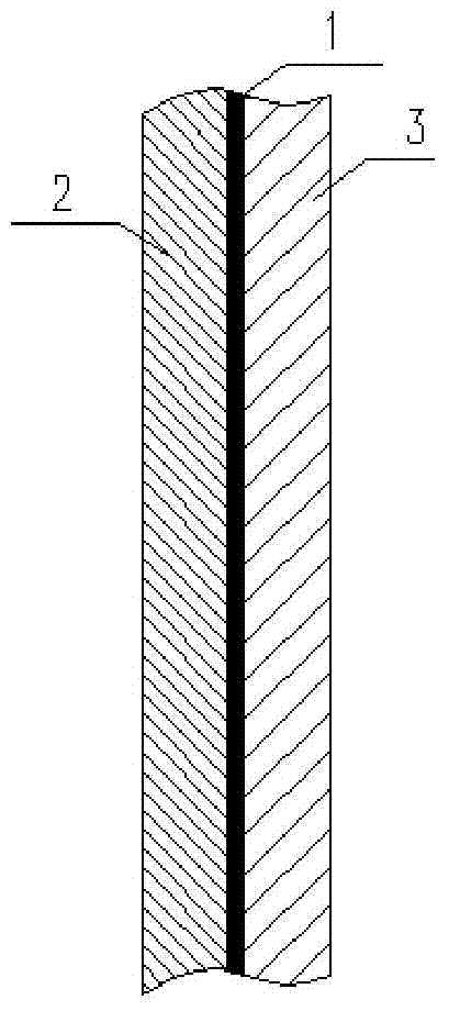
[0029] Select a 12mm thick 304 stainless steel plate and cut it into a stainless steel metal substrate with a size of 300*300mm; 3

[0030] Select a glass-ceramic plate of wollastonite system with a thickness of 15 mm, and cut it into a glass-ceramic plate 2 with a size of 300*300 mm;

[0031] Select 0.36mm~5mm thick PVB film, PU film or EVA film, and cut it into 300*300mm size;

[0032] Stack together in the order of glass-ceramic plate / film / metal substrate;

[0033] Use nylon film or vacuum bag to vacuumize the above three-layer structure, and put it into the autoclave according to the lamination process of the corresponding film, and heat up and increase the pressure;

[0034] After cooling out of the kettle, the glass-ceramic plate and the metal substrate are bonded together by film melting, and the obtained glass-ceramic-metal composite plate is the composite wear-resistant plate for the chute. The structure of gained composite wear-resistant plate sees figure 1 . fig...

Embodiment 2

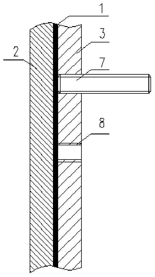
[0036] The difference between this embodiment and the first embodiment is that the glass-ceramic-metal composite plate has threaded holes for setting connecting bolts. Therefore, on the basis of Embodiment 1, first process the φ8mm threaded hole 8 at the corresponding position of the metal substrate of the stainless steel plate according to the design, and then laminate the film in the order of glass-ceramic plate / film / metal substrate. The structure of gained composite wear-resistant plate sees figure 2 . The connecting bolts in this embodiment are stud bolts 7, and one end of the stud bolt 7 is fixedly connected to the metal base plate 3 through the threaded hole 8 to realize assembly with the composite wear-resistant plate. Of course, the composite wear-resistant plate can also be fixed to the installation wall by passing through the installation wall and connecting the threaded hole 8 on the metal base plate 3 during installation.

Embodiment 3

[0038] Select ordinary carbon steel plates with a thickness of 12mm and cut them into metal substrates with a size of 300*300mm;

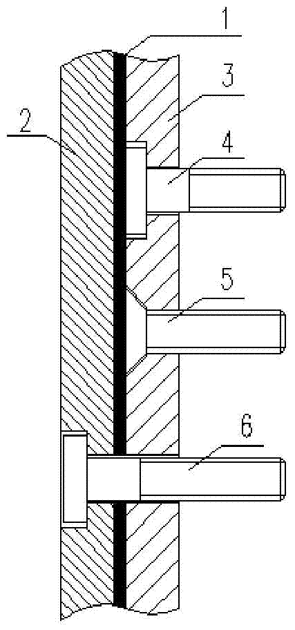
[0039] Process the φ8mm through hole at the corresponding position of the metal substrate according to the design drawing, and process it into a counterbore on the steel plate according to the size of the nut (bolt head) of the φ6-7mm stepped bolt; see image 3 The assembly positions of the bolts 4 and 5 of the two types. Such as image 3 As mentioned above, the shape and size of the counterbore match the shape and size of the nut of the connecting bolt selected. Generally, the cross-section of the nut and its matching counterbore should be non-circular to facilitate the installation operation. The section of the counterbore matched with the bolt 4 is stepped, and the section of the counterbore matched with the bolt 5 is trapezoidal.

[0040] Fill the counterbore with epoxy resin or unsaturated polyester mud, insert the supporting connecting bol...


PUM


Abstract

The invention discloses a composite wear-resistant plate for a chute and a manufacturing method of the composite wear-resistant plate. The composite wear-resistant plate comprises a metal baseplate and a microcrystalline glass plate, the metal baseplate comprises a first surface and a second surface which are opposite, and the microcrystalline glass plate is bonded together with the first surface of the metal baseplate to form a microcrystalline glass-metal composite plate. The composite wear-resistant plate is high in durability.

Description

technical field [0001] The invention relates to the field of chute technology, in particular to a composite wear-resistant plate for a chute and a preparation method thereof. Background technique [0002] The chute is the most commonly used method for conveying raw materials in different processes in the steel, cement, coking and other industries. The above-mentioned raw material transportation has the characteristics of long cycle working period and large material flow. The longer feeding time will easily cause serious wear and tear on the output equipment, especially the chute, and even the phenomenon of being forced to stop for emergency repairs during production. Therefore, it is particularly important to improve the wear resistance and impact strength of the lining material of the chute. [0003] Taking the current blast furnace chute lining board and cement industry chute lining board as examples, the existing chute lining board mainly has two forms: one is integrall...

Claims


Application Information

Patent Timeline
Patent Type & Authority Patents(China)
IPC IPC(8): B32B17/06B32B7/12
CPCB32B7/12B32B17/061B32B2307/554B32B2307/752
Inventor 李要辉黄幼榕王晋珍
Owner BEIJING HANGBO NEW MATERIAL TECH
Why Eureka
Try Eureka