Micro-bridge structure of micro radiation detector and array thereof

A radiation detector and micro-bridge structure technology, applied in the field of micro-electromechanical systems, can solve problems such as fracture, difficult balance of the overall structure of the micro-radiation detector, and warping of pixels

Active Publication Date: 2016-05-11
SHANGHAI INTEGRATED CIRCUIT RES & DEV CENT
View PDF8 Cites 6 Cited by
  • Summary
  • Abstract
  • Description
  • Claims
  • Application Information

AI Technical Summary

Problems solved by technology

In order to allow the bridge deck to receive infrared light to the greatest extent and increase the fill factor (FillFactor), the support columns are generally set to two diagonally placed, but this will make the overall structure of the micro-radiation detector difficult to balance. In the case of poor process control It is very easy to warp or even break the pixel

Method used


Image

  • Micro-bridge structure of micro radiation detector and array thereof
  • Micro-bridge structure of micro radiation detector and array thereof
  • Micro-bridge structure of micro radiation detector and array thereof

Examples


Embodiment 1

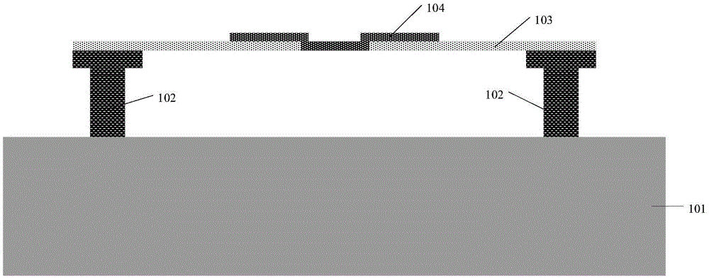
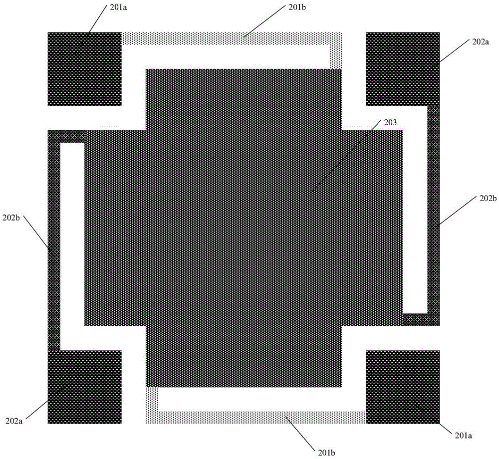
[0039] Please refer to Figure 2a, which is a schematic plan view of the micro-bridge structure of the micro-radiation detector according to Embodiment 1 of the present invention. Among them, the bridge deck 203 is suspended on the semiconductor substrate, and the bridge deck 203 is symmetrical along the X-axis direction and the Y-axis direction, and has a square symmetrical structure. There is a square gap at its four corners, and the four support columns 102 are respectively Set at the position of the square notch. In this embodiment, the first group of beams 201b and the second group of beams 202b are drawn along the four corners of the bridge deck 203, wherein the two opposite first group beams 201b only provide mechanical connection, and the two oppositely arranged second Beam set 202b provides both mechanical and electrical connections. Preferably, in this embodiment, both the first group of beams 201b and the second group of beams 202b have one bend, and in other embo...

Embodiment 2

[0042] Please refer to Figure 3a , which is a schematic plan view of the micro-bridge structure of the micro-radiation detector according to the second preferred embodiment of the present invention. Similar to Embodiment 1, it has a bridge deck 203, a first pair of support columns 201a and a second pair of support columns 202a arranged diagonally, and a first group of beams 201b and a second group of beams 202b connected thereto. The support column 201a and the first group of beams 201b only provide mechanical connection, and the second pair of support columns 202a and the second group of beams 202b provide both mechanical connection and electrical connection; the difference from the first embodiment is that the connection between the beam and the support column The position close to the inner side of the support column, that is, the side close to the bridge deck 203 , preferably, in this embodiment, the distance between the outer edge of the beam and the midpoint of the cros...

Embodiment 3

[0046] Please refer to Figure 4a , which is a schematic plan view of the micro-bridge structure of the micro-radiation detector according to the third preferred embodiment of the present invention. Similar to Embodiment 1, it has a bridge deck 203, a first pair of support columns 201a and a second pair of support columns 202a arranged diagonally, and a first group of beams 201b and a second group of beams 202b connected thereto, 201a and 201b Only provide mechanical connection, the first pair of support columns 201a and the first group of beams 201b only provide mechanical connection, the second pair of support columns 202a and the second group of beams 202b provide both mechanical connection and electrical connection; the difference is that only mechanical The supporting pillars 201a have a larger cross-section, while the supporting pillars 202a that provide both mechanical support and electrical connection have a smaller cross-section. In addition, the connection between th...


PUM


Abstract

The invention belongs to the field of microelectronic mechanical systems in a semiconductor technology, and discloses a micro-bridge structure of a micro radiation detector and an array thereof. The micro-bridge structure comprises a semiconductor substrate, a bridge deck, beams and supporting columns, wherein the bridge deck is suspended on the semiconductor substrate; four beams are respectively led out from corners of the bridge deck; and the four supporting columns are erected on the semiconductor substrate and connected with the bridge deck through the beams. The invention provides the micro-bridge structure of the micro radiation detector and the array thereof, and compared with a traditional structure, since the existing micro-bridge structure is provided with four supporting columns and beams, thus a pixel integral structure is more balanced and a process window is added; when the array is formed by adopting shared supporting columns, a minimum periodic unit only includes one supporting column, and has a higher filling rate, so that the bridge deck can be guaranteed to receive infrared lights to a maximum extent, an excellent structural stability can be obtained, and the micro radiation detector can be guaranteed to have higher sensitivity and signal to noise ratio.

Description

technical field [0001] The invention relates to the field of micro-electromechanical systems in semiconductor technology, in particular to a micro-bridge structure and an array of a micro-radiation detector. Background technique [0002] Substances in nature will radiate infrared signals outward. Micro-radiation detectors are used to receive infrared light radiated by substances, and use the sensitivity of heat-sensitive materials to infrared radiation to detect temperature changes of objects, because they can work at room temperature and It has the advantages of light weight, small size, long life, low cost, low power, fast startup and good stability, etc. It meets the urgent needs of civilian infrared systems and some military infrared systems for long-wave infrared detectors, and has developed rapidly in recent years. Among them, the micro-radiation detector based on the MEMS manufacturing process has low crosstalk and low 1 / f noise, high frame rate, and high working effi...

Claims


Application Information

Patent Timeline
Patent Type & Authority Applications(China)
IPC IPC(8): B81B7/00B81B7/04G01J5/02
CPCB81B7/0009B81B7/04G01J5/022
Inventor 袁超
Owner SHANGHAI INTEGRATED CIRCUIT RES & DEV CENT
Why Eureka
Try Eureka