
Automatic testing method for key parameters of MEMS gyroscope structure

A key parameter, automatic test technology, applied in the direction of measuring devices, instruments, etc., can solve the problems of omission, long test time, extended frequency sweep test time, etc., to achieve the effect of improving efficiency and shortening test time

Active Publication Date: 2016-05-11
BEIJING AUTOMATION CONTROL EQUIP INST
View PDF4 Cites 19 Cited by
  • Summary
  • Abstract
  • Description
  • Claims
  • Application Information

AI Technical Summary

Problems solved by technology

This method is suitable for gyroscopes with a low quality factor. If the gyroscope has a high quality factor, in order to achieve test accuracy, it is necessary to increase the number of frequency sweep points to ensure that the frequency resolution is high enough, and increasing the number of frequency sweep points will greatly prolong the frequency sweep test time, and Higher requirements are placed on system hardware
At the same time, this method also needs to be debugged, changed lines and other operations during the test process, the test time is long and manual intervention is required
[0004] Under variable temperature conditions, such as from -40°C to +85°C, with a temperature change rate of 1°C / min, key parameters of the structure need to be tested at each temperature point, and frequent data debugging and replacement of test connection lines are required, which will consume a lot of energy. Huge workload requires testers to monitor in the middle, otherwise a certain temperature point test will be missed, and the test efficiency is not high
Cannot realize automatic and efficient measurement

Method used


Image

  • Automatic testing method for key parameters of MEMS gyroscope structure
  • Automatic testing method for key parameters of MEMS gyroscope structure
  • Automatic testing method for key parameters of MEMS gyroscope structure

Examples


Embodiment Construction

[0030] Hereinafter, the present invention will be further described in conjunction with the drawings and specific embodiments.

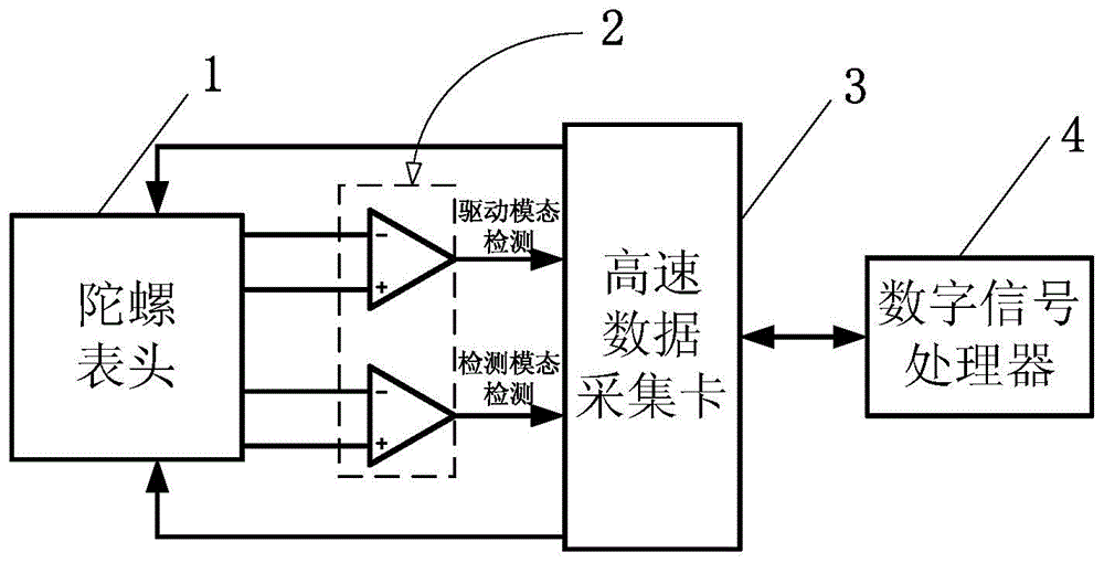
[0031] figure 1 It is a device block diagram for realizing the MEMS gyroscope structure key parameter automatic testing method of the present invention:

[0032] It mainly includes a gyroscope head 1, a test circuit 2, a high-speed data acquisition card 3 and a digital signal processor 4. The gyro meter 1 is connected to the high-speed data acquisition card 3 through the test circuit 2, and the vibration detection signals of the gyro drive mode and the detection mode enter the digital signal processor 4 through the high-speed data acquisition card 3 for processing to obtain the required parameters, and at the same time the digital signal The processor 4 can generate an excitation signal through the acquisition card 3 to drive the gyroscope head 1 .

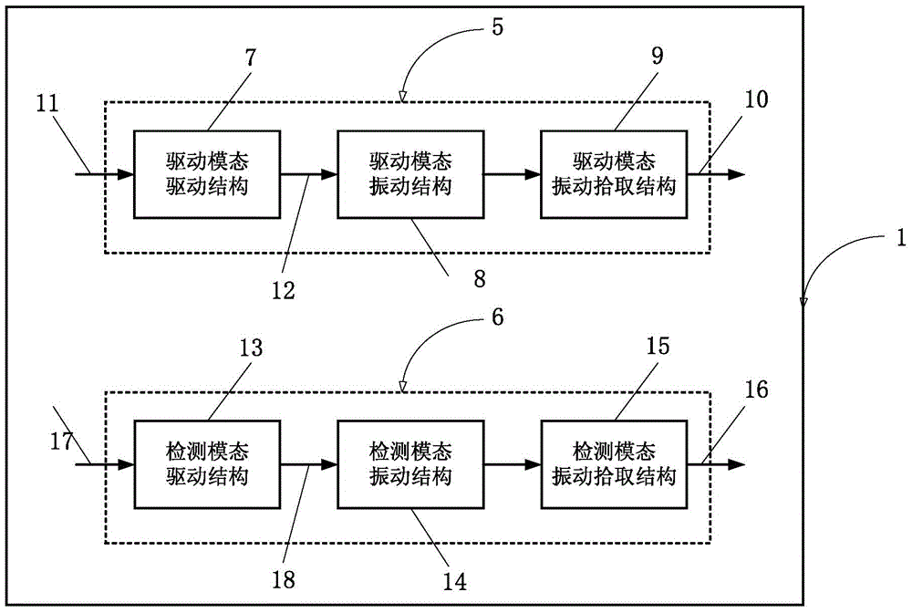
[0033] The MEMS gyroscope targeted by the present invention is a MEMS gyroscope comprising two work...


PUM


Abstract

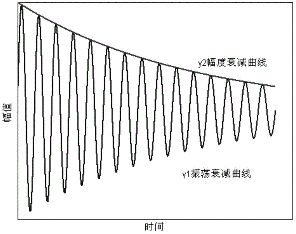
The invention relates to an automatic testing method for key parameters of an MEMS gyroscope structure. The method comprises the following steps: step (1) applying white noise voltage excitation to a driving structure electrode of a driving mode of the MEMS gyroscope so as to generate a driving force; step (2) enabling a vibration collecting structure electrode of the driving mode of the MEMS gyroscope to be connected with a preposition read out circuit, and enabling a response curve to be collected into a digital signal processing machine for FFT treatment so as to obtain resonant frequency fd of the driving mode; step (3) constructing a sine wave according to the resonant frequency fd obtained in the step (2), applying the sine wave to the driving structure electrode of the driving mode, and after determining the gyroscope starts oscillation, collecting an output voltage of the preposition read-out circuit of the driving mode and an output voltage of the preposition read-out circuit of a detection mode so as to obtain a coupling ratio; step (4) removing sine wave excitation, and computing the quality factor Qd of the driving mode through an attenuation curve. According to the automatic testing method disclosed by the invention, the structure key parameters of the resonant frequency, the quality factor, the coupling voltage ratio, the displacement ratio and the like can be automatically tested.

Description

technical field [0001] The invention relates to an automatic testing method, in particular to an automatic testing method for key parameters of MEMS gyro structure. technical background [0002] MEMS gyro is a device with a characteristic size in the order of microns processed by microelectronics technology. It has the advantages of small size, low cost, suitable for batch processing and easy integration with ASIC. MEMS gyroscopes contain vibrating structures, and key structural parameters such as resonant frequency, quality factor Q, and coupling amount will affect the overall performance of the device. Before the instrument assembly, it is necessary to screen the MEMS gyro head, test the key parameters of the structure, and determine the basic performance of the gyro head. In addition to the normal temperature test, it is also necessary to test these structural key parameters under the conditions of variable temperature and variable package pressure to investigate the tem...

Claims


Application Information

Patent Timeline
IPC IPC(8): G01C25/00
Inventor 崔健林梦娜王晓磊郭中洋杨军
Owner BEIJING AUTOMATION CONTROL EQUIP INST
Learn More