Dual-frequency antenna, dual-polarized dual-frequency antenna and preparation method of isolation element

A dual-frequency antenna and isolation component technology, which is applied to antennas, electrical components, and devices that enable antennas to work in different bands at the same time, can solve problems such as difficulty in ensuring product batch consistency, reducing signal-to-noise ratio, and affecting design accuracy. , to achieve high accuracy and batch consistency

Active Publication Date: 2016-05-11
COMBA TELECOM TECH (GUANGZHOU) CO LTD
View PDF6 Cites 5 Cited by
  • Summary
  • Abstract
  • Description
  • Claims
  • Application Information

AI Technical Summary

Problems solved by technology

[0006] If the scheme of the above literature is applied to the high frequency band (such as the mobile communication 700MHz ~ 2700MHz frequency band), because the inductance coil will produce the combined effect of parasitic bypass capacitance and equivalent series resistance in the high frequency band, and the capacitance will also have parasitic bypass inductance in the high frequency band And series resistance effect, and there are differences in the welding process of components. These non-ideal parasitic effects and resistance effects will lead to deviations between actual parameters and ideal parameters, affecting design accuracy, and it is difficult to ensure batch consistency of products
[0007] Patent do

Method used


Image

  • Dual-frequency antenna, dual-polarized dual-frequency antenna and preparation method of isolation element
  • Dual-frequency antenna, dual-polarized dual-frequency antenna and preparation method of isolation element
  • Dual-frequency antenna, dual-polarized dual-frequency antenna and preparation method of isolation element

Examples


Example Embodiment

[0032] The present invention is further described below with reference to the accompanying drawings and exemplary embodiments, wherein like numerals in the drawings refer to like parts throughout. Also, if a detailed description of known art is not necessary to illustrate the features of the present invention, it will be omitted.

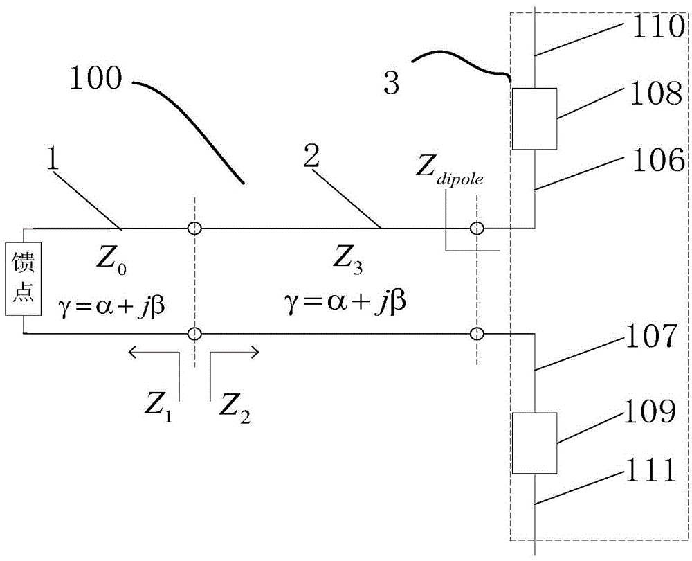
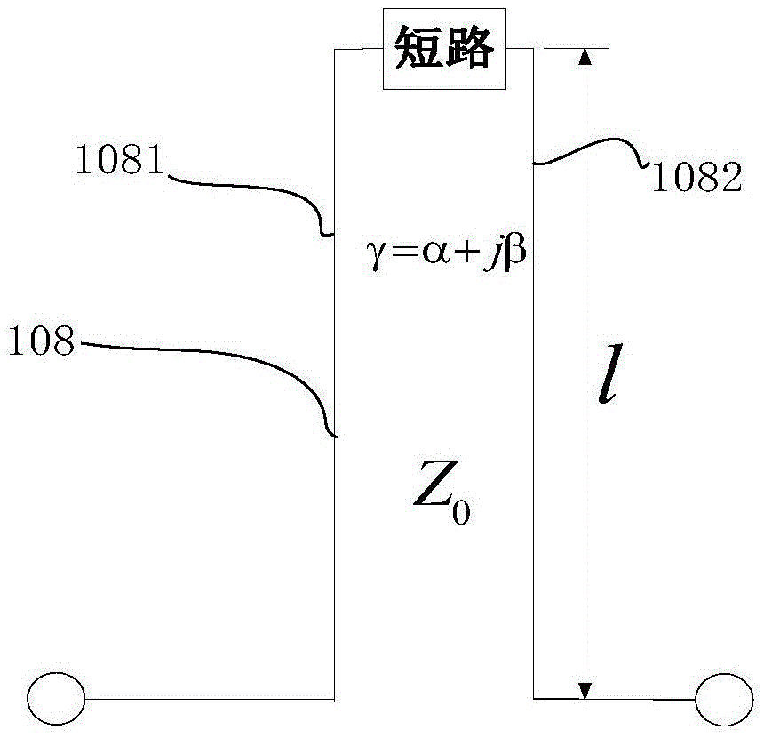
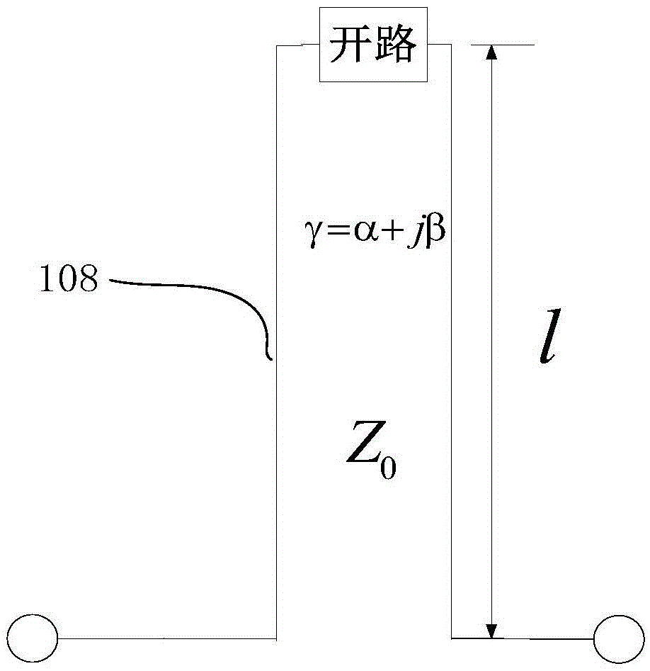
[0033] refer to Figures 1 to 8 , figure 1 The circuit schematic diagram of the dual-frequency antenna of the present invention, figure 2 and image 3 for figure 1 The circuit schematic of the isolation element involved in, where, figure 2 One end of the parallel double wire shown is shorted, image 3 One end of the parallel double line shown is an open circuit.

[0034] The dual-frequency antenna 100 of the present invention includes a feeding unit 1 , a transmission line 2 and a radiating arm unit 3 that are electrically connected in sequence.

[0035] The feeding unit 1 has a feeding point for connecting with an external feeding network,...


PUM


Abstract

The invention relates to a dual-frequency antenna comprising a feed unit, a transmission line and a radiation arm unit which are electrically connected in sequence. The radiation arm unit comprises an internal radiation unit including a first and second high frequency radiation arm, an external radiation unit including a first and second low frequency radiation arm, and two isolation elements arranged between the internal and external radiation unit. One end of the internal radiation unit is connected with the transmission line, and the other end of the internal radiation unit is electrically connected with the external radiation unit through the isolation elements. Each isolation element has a parallel double-line structure with one end open-circuited or short-circuited, and two conductors forming the other end of the parallel double-line of the isolation element are respectively connected with a corresponding high frequency radiation arm and low frequency radiation arm. The dual-frequency antenna realizes high accuracy in transmission and batch consistency in production, improves the defects of an existing technical scheme, and has an advantage of small size.

Description

【Technical field】 [0001] The invention relates to the field of antenna design, in particular to a dual-frequency antenna, a dual-polarization dual-frequency antenna and a preparation method for an isolation element. 【Background technique】 [0002] Different communication systems require transmitting / receiving antennas with different frequency bands. Therefore, the antenna should be able to receive radio signals of multiple frequency bands to be applied to multiple communication systems. For transmitting / receiving radio signals at multiple frequencies, multiple single-frequency antennas or multi-frequency antennas operating on multiple frequencies can be used. However, in terms of improving the space utilization and operability of the communication system, using multi-frequency transmitting / receiving antennas is more beneficial to the integrated design of the communication system than using multiple single-frequency transmitting / receiving antennas. [0003] Patent document C...

Claims


Application Information

Patent Timeline
IPC IPC(8): H01Q5/30H01Q5/50
CPCH01Q5/30H01Q5/50
Inventor 赖展军朱剑青
Owner COMBA TELECOM TECH (GUANGZHOU) CO LTD
Why Eureka
Try Eureka