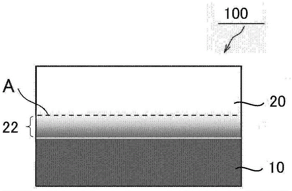
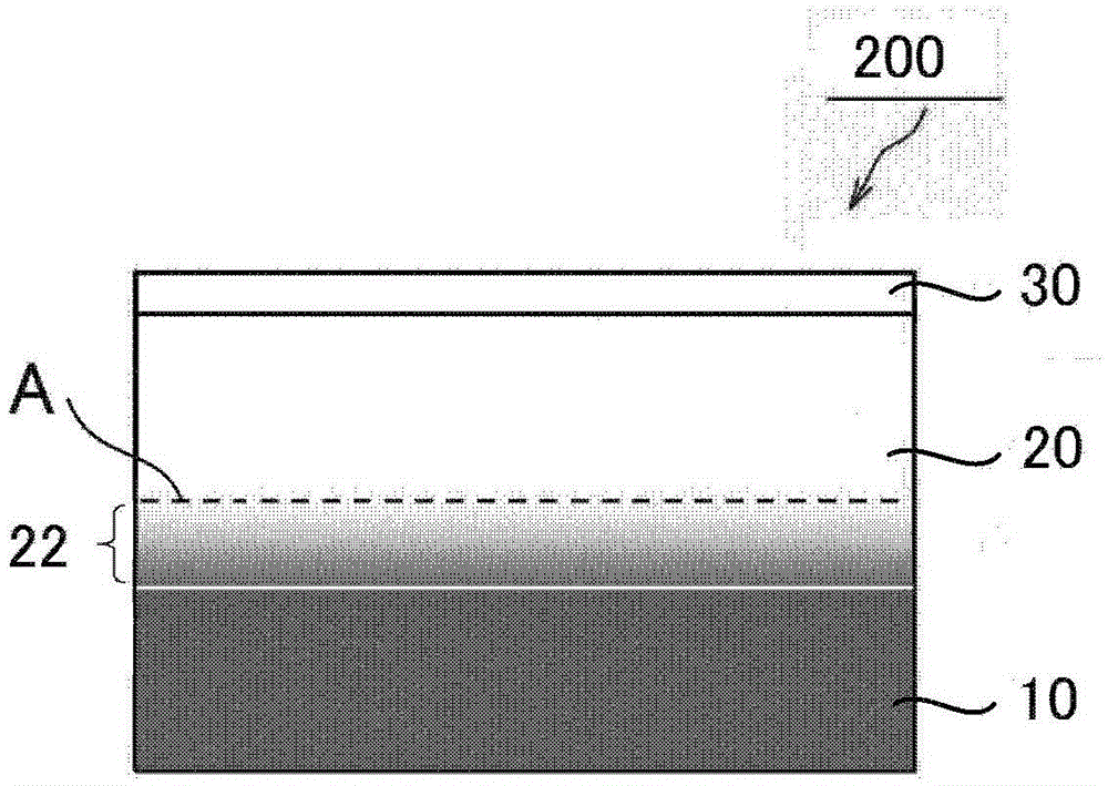
Optical laminate
An optical laminate and hard coating technology, applied in optics, optical elements, nonlinear optics, etc., can solve the problem of insufficient hardness, and achieve the effects of preventing interference spots, sufficient hardness, and simple manufacturing methods
- Summary
- Abstract
- Description
- Claims
- Application Information
AI Technical Summary
Problems solved by technology
Method used
Image
Examples
Embodiment
[0130] Hereinafter, the present invention will be specifically described with examples, but the present invention is not limited by these examples. The evaluation methods in the examples are as follows. In addition, in the examples, unless otherwise indicated, "parts" and "%" are based on weight.
[0131] (1) Refractive index
[0132] Using an Abbe refractometer (trade name: DR-M2 / 1550) manufactured by Atago Corporation, and selecting monobromonaphthalene as an intermediate solution, the refractive index of the base layer and the hard coat layer were measured.
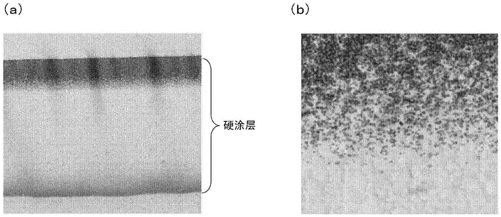
[0133] (2) Thickness and penetration depth of hard coating
[0134] A black acrylic plate (manufactured by Mitsubishi Rayon Co., Ltd., thickness 2 mm) was attached to the substrate layer side of the optical laminates obtained in the examples and comparative examples via an acrylic adhesive having a thickness of 20 μm. Then, using an instant multi-channel photometry system (manufactured by Otsuka Electronics Co., Ltd., trade ...
manufacture example 1
[0158] Production of base film A
[0159] Using a biaxial kneader, 100 parts by weight of the imidized MS resin (weight average molecular weight: 105,000) described in Production Example 1 of JP 2010-284840 A and a triazine-based ultraviolet absorber were mixed at 220°C (Manufactured by ADEKA, trade name: T-712) 0.62 parts by weight were mixed to prepare resin pellets. The obtained resin pellets were dried at 100.5 kPa and 100°C for 12 hours, and extruded from a T-die at a die temperature of 270°C using a uniaxial extruder to form a film (thickness 160 μm). Furthermore, the film was stretched in its conveying direction (thickness 80 μm) in an atmosphere of 150°C, and then stretched in a direction orthogonal to the film conveying direction in an atmosphere of 150°C to obtain a base film A with a thickness of 40 μm ((Meth)acrylic resin film). The obtained base film A had a transmittance of 8.5% for light with a wavelength of 380 nm, an in-plane retardation Re of 0.4 nm, and a th...
Embodiment 1
[0161] 80 parts of urethane acrylate oligomer (manufactured by Daicel-Cytec, product name "KRM8452", Mw=1200, number of functional groups: 10) as a curable compound and pentaerythritol triacrylate (Osaka Organic Chemical Industry Co., Ltd.) Manufacture, product name "Viscoat#300", Mw=298) 20 parts, and containing ZrO 2 Microparticle sol (manufactured by Nissan Chemical Company, product name "NanouseOZ-S30K", solid content: 30%, average particle size: 10nm, refractive index: 2.2, solvent: methyl isobutyl ketone) 100 parts, leveling agent (Manufactured by DIC Corporation, trade name: PC4100) 0.5 part, and 3 parts of photopolymerization initiator (manufactured by CibaJapan, trade name: Irgacure907) were mixed, and methyl isobutyl ketone was used so that the solid content concentration became 50% The dilution is performed to prepare a composition for forming a hard coat layer.
[0162] The obtained hard-coat layer formation composition was apply|coated on the base material film A obt...
PUM
| Property | Measurement | Unit |
|---|---|---|
| glass transition temperature | aaaaa | aaaaa |
| glass transition temperature | aaaaa | aaaaa |
| thickness | aaaaa | aaaaa |
Abstract
Description
Claims
Application Information
 - R&D
- Intellectual Property
- Life Sciences
- Materials
- Tech Scout
- Unparalleled Data Quality
- Higher Quality Content
- 60% Fewer Hallucinations
Browse by: Latest US Patents, China's latest patents, Technical Efficacy Thesaurus, Application Domain, Technology Topic, Popular Technical Reports.
© 2025 PatSnap. All rights reserved.Legal|Privacy policy|Modern Slavery Act Transparency Statement|Sitemap|About US| Contact US: help@patsnap.com


