

optical stack
A technology of optical laminates and hard coatings, applied in optics, optical components, nonlinear optics, etc., can solve problems such as insufficient hardness, and achieve the effects of preventing interference spots, sufficient hardness, and simple manufacturing methods
- Summary
- Abstract
- Description
- Claims
- Application Information
AI Technical Summary
Problems solved by technology
Method used
Image

Examples
Embodiment
[0130] Hereinafter, although an Example demonstrates this invention concretely, this invention is not limited to these Examples. The evaluation methods in Examples are as follows. In addition, in an Example, unless otherwise indicated, "part" and "%" are based on weight.
[0131] (1) Refractive index
[0132] Using an Abbe refractometer (trade name: DR-M2 / 1550) manufactured by Atago Corporation, monobromonaphthalene was selected as an intermediate liquid, and the refractive index of the base material layer and the hard coat layer was measured.
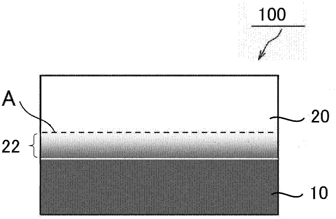
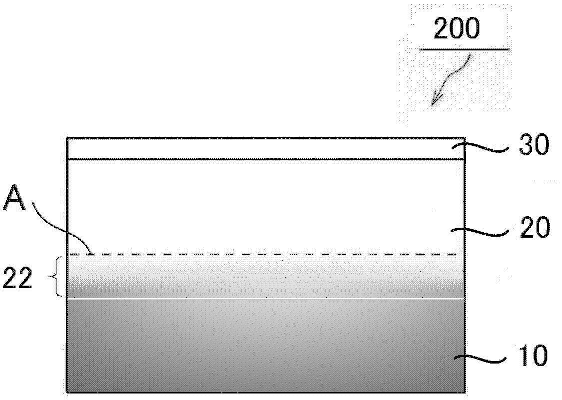
[0133] (2) Thickness and penetration depth of hard coating
[0134] A black acrylic plate (manufactured by Mitsubishi Rayon Corporation, thickness 2 mm) was bonded to the substrate layer side of the optical laminates obtained in Examples and Comparative Examples via an acrylic adhesive with a thickness of 20 μm. Then, using an instant multi-channel photometry system (manufactured by Otsuka Electronics, trade name: MCPD3700), the ref...
manufacture example 1
[0158] Production of base film A
[0159] Using a biaxial kneader, 100 parts by weight of the imidized MS resin (weight average molecular weight: 105,000) described in Production Example 1 of JP-A-2010-284840 and a triazine-based ultraviolet absorber were mixed at 220°C. (ADEKA company make, brand name: T-712) 0.62 weight part was mixed, and the resin pellet was produced. The obtained resin pellets were dried at 100.5 kPa and 100° C. for 12 hours, and extruded from a T-die at a die temperature of 270° C. using a single-screw extruder to form a film (thickness 160 μm). Furthermore, the film was stretched in the conveyance direction (thickness: 80 μm) in an atmosphere of 150° C., and then stretched in a direction perpendicular to the film conveyance direction in an atmosphere of 150° C. to obtain a base film A with a thickness of 40 μm. ((meth)acrylic resin film). The transmittance of the light of the wavelength 380nm of the obtained base film A was 8.5%, the in-plane retarda...
Embodiment 1
[0161] As a curable compound, 80 parts of urethane acrylate oligomer (manufactured by Daicel-Cytec, product name "KRM8452", Mw=1200, number of functional groups: 10) and pentaerythritol triacrylate (Osaka Organic Chemical Industry Co., Ltd. Manufacturing, product name "Viscoat#300", Mw=298) 20 parts, and containing ZrO 2 Microparticle sol (manufactured by Nissan Chemical Co., Ltd., product name "Nanouse OZ-S30K", solid content: 30%, average particle diameter: 10 nm, refractive index: 2.2, solvent: methyl isobutyl ketone) 100 parts, leveling agent (manufactured by DIC Corporation, trade name: PC4100) 0.5 parts, and photopolymerization initiator (manufactured by Ciba Japan Corporation, trade name: Irgacure 907) 3 parts are mixed, and the mode that the solid content concentration becomes 50% utilizes methyl isobutyl Base ketone was diluted to prepare a composition for forming a hard coat layer.
[0162] The obtained composition for hard-coat layer formation was apply|coated on t...
PUM
| Property | Measurement | Unit |
|---|---|---|
| glass transition temperature | aaaaa | aaaaa |
| glass transition temperature | aaaaa | aaaaa |
| thickness | aaaaa | aaaaa |
Abstract
Description
Claims
Application Information