Opto-electric hybrid cable comprising coaxial electric units

一种同轴电单元、光电混合缆的技术,应用在同轴电缆/模拟电缆、电气元件、绝缘电缆等方向,能够解决成本高、外径粗、输电给数量多等问题

Inactive Publication Date: 2016-05-18
王笑梅
View PDF9 Cites 2 Cited by
  • Summary
  • Abstract
  • Description
  • Claims
  • Application Information

AI Technical Summary

Problems solved by technology

[0007] However, the above-mentioned photoelectric composite cables all have the following defects: too many power transmission channels, too complicated structure, thick outer diameter, high cost, etc.

Method used


Image

  • Opto-electric hybrid cable comprising coaxial electric units
  • Opto-electric hybrid cable comprising coaxial electric units
  • Opto-electric hybrid cable comprising coaxial electric units

Examples


Embodiment 1

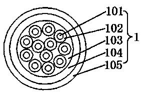
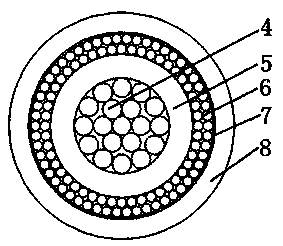
[0026] please see Figure 1 to Figure 3, a photoelectric hybrid cable with a coaxial electrical unit, which is composed of a cable core, a shielding layer 12 covering the cable core, and an outer sheath 13 that is extruded and coated outside the shielding layer. Layer and the outer layer of the cable core located outside the inner layer of the cable core; it is characterized in that the inner layer of the cable core is composed of a central reinforcement 9, four inner coaxial electrical units distributed along the outer edge of the reinforcement and a The filling rope 10 in the outer gap of the adjacent inner layer coaxial electric unit is formed, and each inner layer coaxial electric unit is composed of an inner conductor 4, an insulating layer 5 covering the inner conductor, and an outer layer outside the insulating layer. Conductor 6, insulating tape 7 located outside the outer conductor, and inner sheath 8 coated outside the insulating tape by extrusion molding. On the cr...

Embodiment 2

[0063] please see Figure 4 , and refer to Figure 1 to Figure 3 , the photoelectric hybrid cable with the coaxial electric unit is basically the same as the implementation example 1, the difference is that the solid filling strip can be other multiple; it can also be one; it can also be like Figure 4 Also has a small solid filler strip to round out the outer layer of the cable core.

[0064] Figure 4 The medium and small solid filling strips are located next to the ground wire and in the middle of the two solid filling strips 2 .

[0065] In the present invention, the coaxial power line unit and the optical cable unit are organically twisted into a cable core, the cable core is covered with a metal shielding tape, and a layer of plastic sheath is extruded outside the tape; it is a 4G base station signal transmission system. The processing unit BBU (BasedBandUnit) is ideal for transmitting optical signals and providing power supply cables for the remote radio unit RRU (Re...


PUM


Abstract

The present invention belongs to the technical field of cables and particularly relates to an opto-electric hybrid cable comprising coaxial electric units. The cable is formed by a cable core, a shielding layer which coats the cable core, and an outer sheath which is extruded outside the shielding layer. The cable core is formed by a cable core inner layer and a cable outer layer outside the cable core inner layer and is characterized in that the cable core inner layer is formed by a reinforcing member in the center, multiple inner layer coaxial electric units distributed along the outer edge of the reinforcing member, and filling ropes in the external gaps between the adjacent inner layer coaxial electric units, and the cable core outer layer is formed by multiple outer layer coaxial electric units, multiple optical cable units, multiple solid filling strips, a ground wire and a rip cord. The invention also discloses a manufacturing method of the opto-electric hybrid cable. The cable and the method have the advantages of wide application, good shielding performance, good mechanical performance, a smaller diameter, lower cost, easy construction, and the simple manufacturing method.

Description

[0001] This application is a divisional application for an invention patent titled: Optical-electrical hybrid cable with coaxial electric unit and its manufacturing method, application date: December 18, 2014, and application number: 201410785982.X. technical field [0002] The invention belongs to the technical field of cables, and in particular relates to a photoelectric hybrid cable with a coaxial electric unit and a manufacturing method thereof. Background technique [0003] With the rapid development of the communication industry, the application of optical-electrical hybrid cables is increasing, and a lot of research and development has been carried out on optical-electrical hybrid cables at home and abroad. [0004] For example, the Chinese patent titled: A high tensile and flame retardant photoelectric composite cable, and the application number is: CN201310323268.4 discloses a high tensile and flame retardant photoelectric composite cable, which includes an optical c...

Claims


Application Information

Patent Timeline
Patent Type & Authority Applications(China)
IPC IPC(8): H01B7/00H01B7/17H01B11/06H01B11/22
CPCH01B7/00H01B7/04H01B7/17H01B7/18H01B7/1825H01B11/06H01B11/18H01B11/1808H01B11/22H01B13/00H01B13/02H01B13/14H01B13/24
Inventor 宋乐乐
Owner 王笑梅
Why Eureka
Try Eureka