Anti-phase unequal power divider based on parallel coupling structure

A parallel coupling and power divider technology, applied in waveguide-type devices, circuits, connecting devices, etc., can solve the problems of unfavorable popularization and application of wireless communication systems, high isolation, low loss, etc., and achieve good control ability and low production cost. , the effect of high isolation

Inactive Publication Date: 2016-05-18
NANJING UNIV OF SCI & TECH
View PDF2 Cites 6 Cited by
  • Summary
  • Abstract
  • Description
  • Claims
  • Application Information

AI Technical Summary

Problems solved by technology

[0006] In a word, the problem existing in the prior art is that the anti-phase unequal power divider cannot take into account simple structure, low loss, high isolation, small size and good port matching characteristics, which is not conducive to popularization and application in modern wireless communication systems

Method used


Image

  • Anti-phase unequal power divider based on parallel coupling structure
  • Anti-phase unequal power divider based on parallel coupling structure
  • Anti-phase unequal power divider based on parallel coupling structure

Examples


Embodiment 1

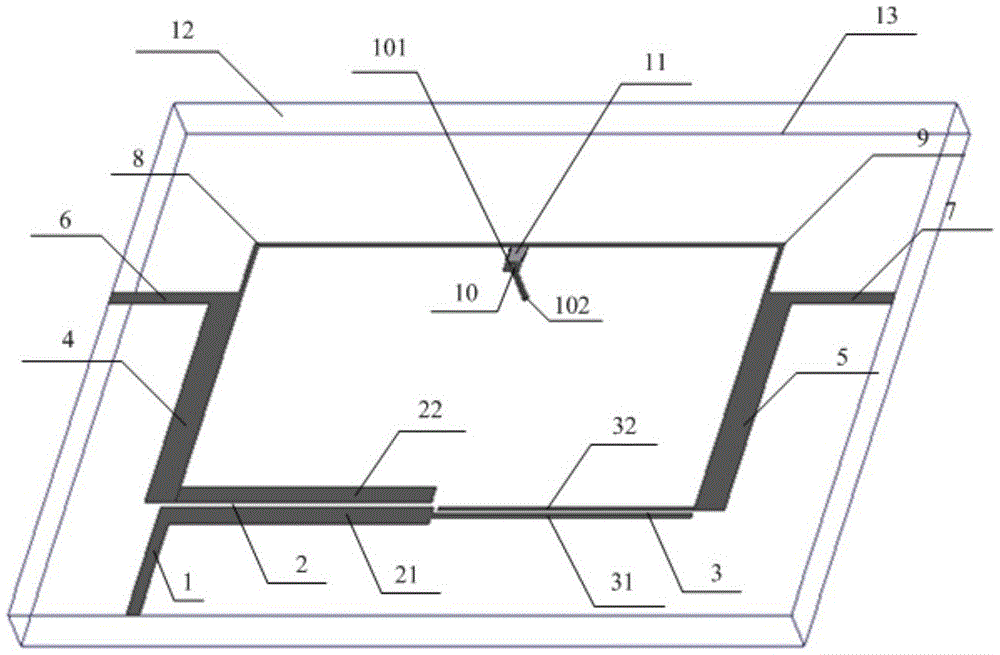
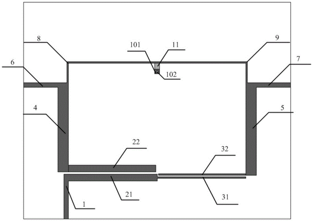
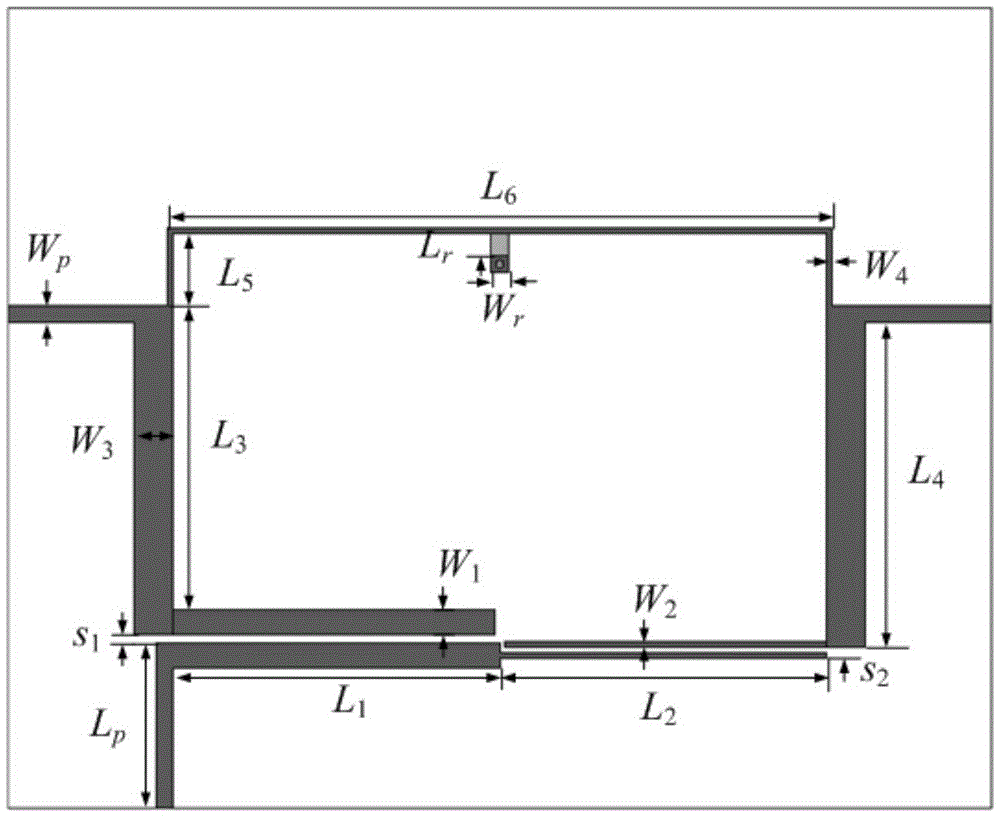
[0041] The structure of the anti-phase unequal power divider based on the parallel coupling structure is as follows figure 1 As shown, the top view is as figure 2 As shown, the relevant dimensions and specifications are as follows image 3 shown. The dielectric substrate 6 used has a relative permittivity of 10.2, a thickness of 0.635 mm, and a loss tangent of 0.0023. combine image 3 , the size parameters of the power divider are as follows: W p = 0.6mm, W 1 = 0.9mm, W 2 = 0.2mm, W 3 = 1.4mm, W 4 = 0.2mm, W r =0.7mm,L 1 =11.7mm,L 2 =11.7mm,L 3 =11.1mm,L 4 =11.85mm,L 5 =2.6mm,L r = 0.8mm, s 1 = 0.3mm, s 2 = 0.2 mm. The total area of ​​the unequal anti-phase power divider excluding the 50 ohm microstrip line conduction band is 16×26.6mm 2 , the corresponding guide wavelength size is 0.34λ g ×0.56λ g , where λ g is the guided wavelength corresponding to the center frequency of the passband.

[0042] The power divider of this example is modeled and simulate...


PUM


Abstract

The invention discloses an anti-phase unequal power divider based on a parallel coupling structure. The anti-phase unequal power divider includes a rectangular medium substrate of which a lower surface is provided with a metal ground plate. An upper surface of the medium substrate is provided with an input terminal feed line, a first output terminal feed line, and a second output terminal feed line. A first parallel coupling structure and a first 1 / 4 wavelength transmission line are arranged between the input terminal feed line and the first output terminal feed line. A second parallel coupling structure and a second 1 / 4 wavelength transmission line are arranged between the input terminal feed line and the second output terminal feed line. A third 1 / 4 wavelength transmission line, a fourth 1 / 4 wavelength transmission line, and a resistor are also arranged between the first output terminal feed line and the second output terminal feed line. The resistor is connected to the ground plate on the lower surface of the medium substrate through a metal through hole in the medium substrate. The anti-phase unequal power divider has simple structure, low loss, high isolation, and small phase deviation.

Description

technical field [0001] The invention relates to the technical field of microwave passive devices, in particular to an anti-phase unequal power divider based on a parallel coupling structure with simple structure, low loss, high isolation and small phase deviation. Background technique [0002] Power dividers, also known as power dividers, play a very important role in the feed network of wireless communication systems. In recent years, the research on the power splitter has been deepened, especially the research on the equal power splitter, but the research on the unequal and anti-phase power splitter, which plays an important role in the beamforming of the antenna array, is relatively less. The unequal power feed can effectively suppress the excessive side lobe level of the antenna, and the differential signal has good anti-noise ability and high signal-to-noise ratio. The traditional RF front-end circuit adopts the method of combining unequal power divider and inverting c...

Claims


Application Information

Patent Timeline
IPC IPC(8): H01P5/12H01P5/16
CPCH01P5/12H01P5/16
Inventor 王雪道刘倩文王建朋黄烽
Owner NANJING UNIV OF SCI & TECH
Why Eureka
Try Eureka