Underwater acoustic signal real-time extraction method based on laser orthogonal polarization interference technology

An underwater acoustic signal and orthogonal polarization technology, which is applied in the direction of measuring ultrasonic/sonic/infrasonic waves, measuring devices, instruments, etc., can solve the problem that real-time extraction of underwater acoustic signals cannot be realized, and it is difficult to meet the needs of large-scale underwater activities. problems with detection, lack of mobility, etc.

Active Publication Date: 2016-05-25
HARBIN INST OF TECH
View PDF7 Cites 18 Cited by
  • Summary
  • Abstract
  • Description
  • Claims
  • Application Information

AI Technical Summary

Problems solved by technology

[0003] The present invention is to solve the lack of mobility of the existing methods, it is difficult to meet the detection of large-scale underwater sound sources, only the static characteristics of underwater sound sour

Method used


Image

  • Underwater acoustic signal real-time extraction method based on laser orthogonal polarization interference technology
  • Underwater acoustic signal real-time extraction method based on laser orthogonal polarization interference technology
  • Underwater acoustic signal real-time extraction method based on laser orthogonal polarization interference technology

Examples


specific Embodiment approach 1

[0041] Specific embodiment one: a kind of real-time extraction method of underwater acoustic signal based on laser orthogonal polarization interference technology of the present embodiment, it is realized according to the following steps:

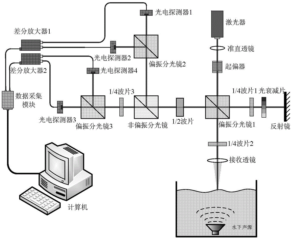
[0042] 2. Build a passive homodyne interferometer system:

[0043] The passive homodyne interferometer system includes laser orthogonal polarization interference optical path, detection signal processing circuit and computer terminal;

[0044] Wherein, the laser orthogonal polarization interference optical path includes a laser, a collimating lens, a polarizer (such as a Glan Taylor prism), a polarizing beam splitting prism 1, a polarizing beam splitting prism 2, a polarizing beam splitting prism 3, a non-polarizing beam splitting mirror, and a receiving lens , 1 / 4 wave plate 1, 1 / 4 wave plate 2, 1 / 4 wave plate 3, 1 / 2 wave plate, light attenuation plate and reflector;

[0045] The detection signal processing circuit includes a photodetecto...

specific Embodiment approach 2

[0066] Embodiment 2: This embodiment differs from Embodiment 1 in that: the vibration direction of the S light in step 3 is along the Y axis, and the vibration direction of the P light is along the X axis.

[0067] Other steps and parameters are the same as those in Embodiment 1.

specific Embodiment approach 3

[0068] Specific implementation mode three: the difference between this implementation mode and specific implementation mode one or two is that step nine adopts the demodulation method to obtain the phase of the detection signal as follows:

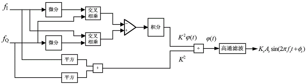
[0069] (1) Use such as figure 2 The shown processing flow (that is, the DCM demodulation flow): two orthogonal signals f I with f Q have the same phase, the phase of the two signals is denoted as Then the two quadrature signals f I with f Q After differentiation and cross multiplication, the two paths can be expressed as: and

[0070] (2) The signal obtained by the two-way differential cross multiplication is then differentially amplified and integrated to obtain the phase of the detection signal Proportional to a signal, the proportionality factor is K 2 , or two quadrature detection signals f I with f Q The aforementioned proportional coefficient K can be obtained by adding squares 2 ;

[0071] (3) Divide the signal obta...


PUM


Abstract

The invention provides an underwater acoustic signal real-time extraction method based on the laser orthogonal polarization interference technology, relating to the underwater acoustic signal real-time extraction method based on the laser orthogonal polarization interference technology. An existing method lacks flexibility, the detection of an underwater wide range moving sound source can not be satisfied, only the detection of the static characteristic of an underwater sound source can be carried out, the real-time extraction of an underwater sound signal can not be realized, and the above problems are solved by the method of the invention. A passive homodyne interferometer system is constructed; an initial coordinate system is established; a laser outputs a single-frequency laser beam to go through a collimating lens and a polarizer to be linearly polarized light, a 45-degree angle is formed by the vibration direction of the linearly polarized light and an X axis, the linearly polarized light goes through a polarized beam splitting prism 1 to be splitted into two beams of polarized light whose vibration directions are perpendicular to each other, and the polarized light is marked as S light and P light; the S light is reflected by the polarized beam splitting prism 1 as reference light, P light is used as detection light, photodetectors detect signals, and the phases of the detected signals are obtained by using a demodulation way. The method is applied to the field of underwater signals.

Description

technical field [0001] The invention relates to a method for real-time extraction of underwater acoustic signals based on laser orthogonal polarization interference technology. Background technique [0002] Optical means are the mainstream technical means for underwater acoustic signal detection. Due to the large power attenuation when light waves propagate in water, optical technology is subject to certain limitations in the detection of underwater sound fields, and technical methods such as laser interference cannot be directly applied to underwater environment, but laser technology can still be indirectly applied to the detection of underwater sound fields. At present, there are three main forms of detection of underwater acoustic signals by means of laser technology: one is to use various structures of fiber optic hydrophones and multi-element fiber optic hydrophone arrays to directly detect underwater sound fields; the other is to use underwater sound sources The acqui...

Claims


Application Information

Patent Timeline
IPC IPC(8): G01H9/00
CPCG01H9/00
Inventor 张晓琳张烈山刘刚唐文彦
Owner HARBIN INST OF TECH
Why Eureka
Try Eureka