

Transport vehicle and control method for transport vehicle
A technology for transporting vehicles and vehicles, applied in the field of transporting vehicles and the control of transporting vehicles, can solve problems such as damage to transporting vehicles, decline in productivity at the excavation site, and obstacles to quarrying transport operations, and achieve the effects of suppressing the decline in work efficiency and reducing damage.
- Summary
- Abstract
- Description
- Claims
- Application Information
AI Technical Summary
Problems solved by technology
Method used
Image


Examples
no. 1 approach
[0038] The first embodiment will be described.
[0039] (excavation site of the mine)
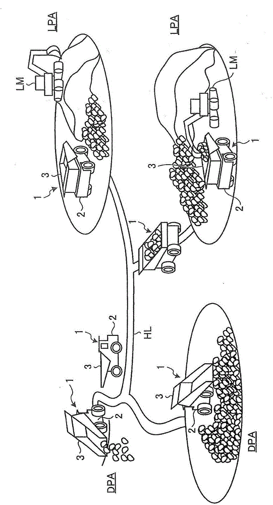
[0040] figure 1 It is a schematic diagram showing an example of an excavation site of a mine where the transportation vehicle of this embodiment operates. The transportation vehicle is a dump truck 1 including a vehicle 2 and a vessel 3 provided on the vehicle 2 . The dump truck 1 transports cargo loaded in the container 3 . The cargo includes at least one of excavated quarry, sand and ore.
[0041] The excavation site of the mine is provided with a loading area LPA, a soil dumping area DPA, and a running road HL communicating with at least one of the loading area LPA and the soil dumping area DPA. The dump truck 1 can travel on at least a part of the loading yard LPA, the dumping yard DPA, and the traveling road HL. The dump truck 1 can travel on the travel road HL and move between the loading area LPA and the dumping area DPA.
[0042] At the loading dock LPA, the container 3 is loa...
no. 2 approach
[0179] A second embodiment will be described. In the following description, the same reference numerals are assigned to the same or equivalent components as those of the above-mentioned embodiment, and the description thereof will be simplified or omitted.
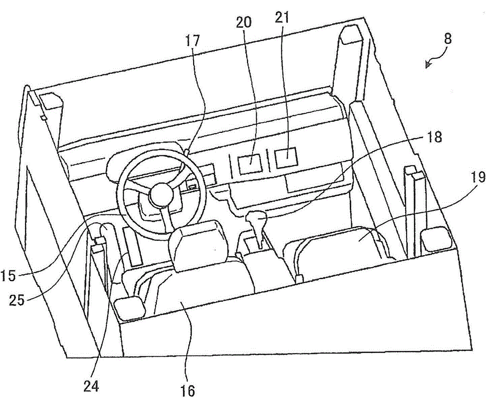
[0180] Figure 13 It is a schematic diagram which shows an example of the control system 300B of this embodiment. The control system 300B has: a first operation unit 41 arranged in the cab 8 ; and a second operation unit 42 arranged in the cab 8 . The first operation unit 41 and the second operation unit 42 are operated by the operator WM. An operation signal Ra generated by operating the first operation unit 41 is output to the control device 30 . The operation signal Rb generated by operating the second operation unit 42 is output to the control device 30 .
[0181] as reference figure 1 As described above, cargo is loaded into the container 3 at the loading area LPA of the mine. The dump truck 1 in the loaded stat...
no. 3 approach
[0189] A third embodiment will be described. In the following description, the same reference numerals are assigned to the same or equivalent components as those of the above-mentioned embodiment, and the description thereof will be simplified or omitted.
[0190] Figure 14 It is a flowchart showing an example of the control method of the dump truck 1 according to the present embodiment. The detection result of the running state detection device 10 is output to the control device 30, and the control device 30 acquires information on the running speed Vt of the dump truck 1 (step SB1).
[0191] Similar to the above-mentioned embodiment, the detection period of the traveling state detection device 10 is Gt (for example, not less than 1 ms and not more than 100 ms). The running state detection device 10 continues to output detection results to the control device 30 at predetermined time intervals Gt. The control device 30 acquires the detection result. The control device 30 ...
PUM
 Abstract
Description
Claims
Application Information