Blow-by gas treatment device for internal combustion engine

一种处理装置、内燃机的技术,应用在燃烧空气/燃烧-空气处理、内燃活塞发动机、燃烧发动机等方向,能够解决吸入空气量测量误差等问题,达到降低测量误差、抑制压力脉动的效果

Active Publication Date: 2016-05-25
NISSAN MOTOR CO LTD
View PDF7 Cites 3 Cited by
  • Summary
  • Abstract
  • Description
  • Claims
  • Application Information

AI Technical Summary

Problems solved by technology

[0005] As described above, in the structure in which the fresh air introduction passage is connected between the throttle valve of the intake passage and the air flow meter, there is a problem that the periodic pressure change in the crankcase, that is, the pressure pulsation of the blow-by air passes through the The fresh air is introduced into the passage and transmitted to the intake passage side, causing errors in the measurement of the intake air volume through the air flow meter
In particular, when an air flow meter with high responsiveness is used, in a low-load region (idle time, etc.) where the amount of intake air is small, there is a large influence of the pulsation of the leak air

Method used


Image

  • Blow-by gas treatment device for internal combustion engine
  • Blow-by gas treatment device for internal combustion engine
  • Blow-by gas treatment device for internal combustion engine

Examples


Embodiment Construction

[0017] Hereinafter, an embodiment of the present invention will be described in detail based on the drawings.

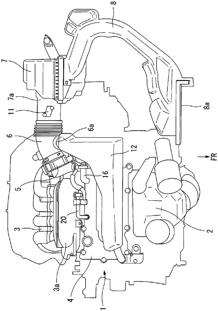
[0018] figure 1 It is a plan view showing an automotive internal combustion engine 1 including an intake system and having a blow-by gas treatment device according to the present invention. The internal combustion engine 1 is mounted in an engine compartment at the front of the vehicle in a so-called transverse position (arrangement in which the central axis of the crankshaft extends in the vehicle width direction), and the exhaust manifold 2 is located on the front side of the vehicle (indicated by reference numeral FR in the figure). The intake manifold 3 is located on the rear side of the vehicle. A header portion 3a forming a part of the intake manifold 3 is disposed adjacent to the cylinder head cover 4 on the vehicle rear side of the cylinder head cover 4, and the throttle chamber 5 is connected to an inlet at one end of the header portion 3a in the longitudin...


PUM


Abstract

A resonator (12) for reducing intake air noise is connected to an intake air duct (6) connecting a throttle chamber (5) and an air cleaner case (7). This blow-by gas treatment device is equipped with a fresh air introduction passage comprising a fresh air introduction hose (16), and a blow-by gas passage comprising a blow-by gas hose (20), with the fresh air introduction hose (16) connecting the cylinder head (4) and the resonator (12). A connector part (15) of the resonator (12) to which the fresh air introduction hose (16) is connected is equipped with an orifice (21), which is formed integrally as a part of a synthetic resin lower body (13). Pulsation is effectively reduced by the throttling effect of the orifice (21) and the expansion effect of the resonator (12).

Description

technical field [0001] The present invention relates to an improvement of a blow-by gas treatment device for an internal combustion engine, which guides the blow-by gas in the crankcase of the internal combustion engine into an intake system and burns the blow-by gas in a combustion chamber. Background technique [0002] Patent Document 1 discloses a blow-by air treatment device for an internal combustion engine, which has: a fresh air introduction passage for introducing fresh air into the crankcase from the upstream side of the throttle valve of the intake passage; The blow-by gas is discharged from the inside of the crankcase to the downstream side of the throttle valve in the intake passage. One end of the fresh air introduction passage is connected between a throttle valve of the intake passage and an air flow meter located upstream therefrom. [0003] In the blow-by gas processing device described above, fresh air is introduced into the crankcase due to a pressure dif...

Claims


Application Information

Patent Timeline
Patent Type & Authority Applications(China)
IPC IPC(8): F01M13/00
CPCF01M11/08F01M13/022F01M13/028F01M13/0416F01M2013/0488F02M25/06F02M35/10222F02M35/1261F02M35/1288Y02T10/12
Inventor 池谷洁
Owner NISSAN MOTOR CO LTD
Why Eureka
Try Eureka