Low-energy consumption oiling agent blending tank

A technology for mixing tank and oil consuming agent, applied in mixer accessories, dissolving, mixer and other directions, can solve the problems of high energy consumption, heat loss, and no thermal insulation measures in the jacket cavity, so as to improve the heat exchange speed, Excellent thermal insulation performance, improving the effect of thermal insulation

Inactive Publication Date: 2016-06-01
孙萍
View PDF0 Cites 1 Cited by
  • Summary
  • Abstract
  • Description
  • Claims
  • Application Information

AI Technical Summary

Problems solved by technology

During use, it is found that the existing oil preparation tank has the following defects: the jacket cavity has no heat insulation measures, resulting in a large amount of heat loss and high energy consumption

Method used


Image

  • Low-energy consumption oiling agent blending tank
  • Low-energy consumption oiling agent blending tank

Examples


Embodiment Construction

[0018] The present invention will be further described below according to the accompanying drawings and in conjunction with the embodiments.

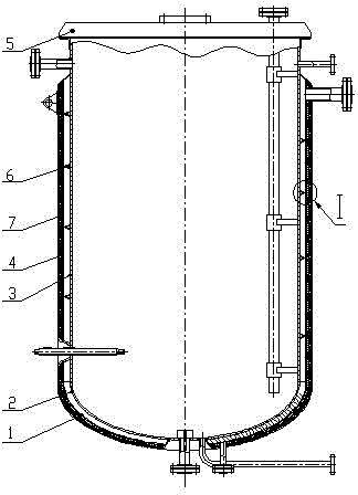
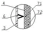
[0019] The low energy consumption oil preparation tank shown in the accompanying drawings includes an outer cylinder head 1, an inner cylinder head 2, an inner cylinder body 3, an outer cylinder body 4, a top cover 5, and a deflector plate 6; the top cover 5 is placed inside The top of the cylinder 3; the outer cylinder 4 fits on the inner cylinder 3, the inner cylinder head 2 is welded and fixed on the lower end of the inner cylinder 3, and the outer cylinder head 1 is welded and fixed on the lower end of the outer cylinder 4; the outer cylinder 4. A jacket cavity is formed between the outer cylinder head 1, the inner cylinder body 3 and the inner cylinder head 2, and the upper end of the jacket cavity is sealed to form a closed cavity; the outer wall of the jacket cavity is provided with a heat insulation layer 7; The heat insulation ...


PUM


Abstract

The invention discloses a low-energy consumption oiling agent blending tank. The tank comprises an outer cylinder head, an inner cylinder head, an inner cylinder, an outer cylinder, a top cover and a guide plate. The top cover is arranged at the top of the inner cylinder. The outer cylinder sleeves the inner cylinder. The inner cylinder head is welded and fixed to the lower end of the inner cylinder. The outer cylinder head is welded and fixed to the lower end of the outer cylinder. The outer cylinder, the outer cylinder head, the inner cylinder and the inner cylinder head form a jacket cavity. The upper end of the jacket cavity is sealed to form an enclosed cavity. The guide plate is arranged in the jacket cavity and helically coils the outer wall of the inner cylinder from top to bottom. The outer wall of the jacket cavity is provided with a heat insulation layer. The heat insulation layer has a two-layer composite structure, an inner heat insulation layer of the two-layer composite structure is glass fiber heat insulation cotton and an outer heat insulation layer is a vacuum insulated plate. The helical line formed through the guide plate is a pitch-variable helical line and the pitch is increased from top to bottom and the cross section of the guide plate is a V-shaped structure. The low-energy consumption oiling agent blending tank has the advantages of less heat lost, low energy consumption and high heat exchange efficiency.

Description

technical field [0001] The invention relates to the field of spinning oil preparation and supply equipment, in particular to an oil preparation tank. Background technique [0002] The existing oil preparation tank is a double-layer cylinder structure with a jacket cavity, and a spiral deflector is arranged in the jacket cavity to guide the flow of heating steam. During use, it is found that the existing oil preparation tank has the following defects: the jacket cavity has no heat insulation measures, resulting in a large amount of heat loss and high energy consumption. Contents of the invention [0003] Aiming at the deficiencies of the prior art, the present invention proposes a low-energy oil preparation tank that can significantly reduce heat loss and consume less energy. [0004] The present invention achieves technical goals through the following technical solutions. [0005] The low-energy consumption oil preparation tank includes an outer cylinder head, an inner c...

Claims


Application Information

Patent Timeline
Patent Type & Authority Applications(China)
IPC IPC(8): B01F15/00B01F15/06
Inventor 孙萍
Owner 孙萍
Why Eureka
Try Eureka