Circulating fluidized bed with semi-conical descending section

A circulating fluidized bed and semi-conical technology, applied in the field of circulating fluidized bed, can solve the problems of throttling, unstable fluidization, inability to eliminate throttling, and affecting the long-term stable operation of industrial devices.

Inactive Publication Date: 2016-06-01
ZHEJIANG UNIV
View PDF11 Cites 2 Cited by
  • Summary
  • Abstract
  • Description
  • Claims
  • Application Information

AI Technical Summary

Problems solved by technology

The reason is found that when the polymer particles in the descending section are transferred to the ascending section in a moving bed state, air plugs are easily formed at the bottom of the descending section, which in turn causes unstable fluidization phenomena such as throttling.
On the one hand, the occurrence of throttling causes the particles in the descending section to be pushed upwards. If the material seal is formed again, it will take a period of time for the particles to fall back, which makes the establishment of particle circulation longer; on the other hand, a large number of particles i

Method used


Image

  • Circulating fluidized bed with semi-conical descending section
  • Circulating fluidized bed with semi-conical descending section
  • Circulating fluidized bed with semi-conical descending section

Examples


Embodiment 1

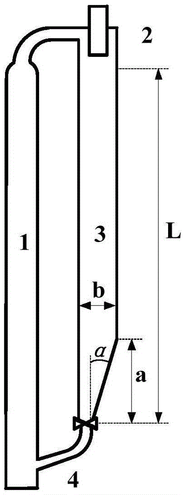
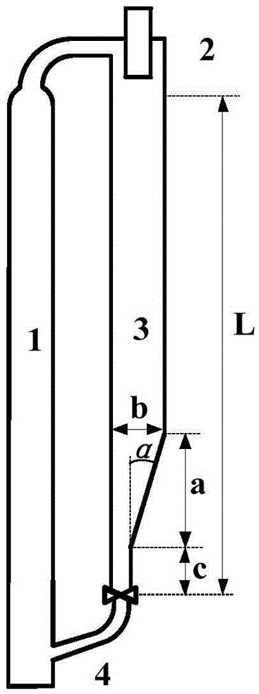
[0020] like figure 1 As shown, a semi-conical descending circulating fluidized bed of the present invention includes a lifting section 1, a cyclone separation section 2, a semi-conical descending section 3, and a particle circulation section 4. The preferred semi-conical structure in Example 1 meets the following conditions: the semi-conical structure is narrow at the bottom and wide at the top, the ratio of the upper and lower widths is 4, the ratio of the height b of the semi-cone to the height L of the descending section is 0.2, and the conical structure of the semi-cone is 0.2. The angle α is 50°, and the distance between the starting position of the semi-conical bottom and the bottom of the descending section is 0. The superficial velocity of circulating gas at the bottom of the lift section is 7.86m / s.

[0021] Figure 4 (a) and (b) are the velocity vector diagrams of gas phase and particle phase in the descending section of this embodiment under the state of a large a...

Embodiment 2

[0023] Embodiment 2 (comparative example):

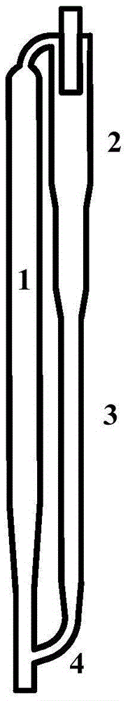
[0024] like figure 2 As shown, the descending section is an axisymmetrically distributed circulating fluidized bed, including a lifting section 1, a cyclone separation section 2, a descending section 3, and a particle circulation section 4. The superficial gas velocity at the bottom of the lifting section is 7.86m / s. Figure 6 It is the variation of particle phase concentration distribution with time when the descending section of this example is in a state of a large amount of blow-by gas. Depend on Figure 6 It can be seen that the blow-by gas in the descending section forms an air plug at the bottom, which makes the particle phase in the descending section form a throttling fluidization state, and the particle phase in the descending section is pushed upward by the throttling gas plug, which on the one hand aggravates the entrainment of the particle phase in the descending section; On the one hand, the time for the particles ...


PUM


Abstract

The invention discloses a circulating fluidized bed with a semi-conical descending section. The bottom of the descending section is semi-conical, is relatively narrow in bottom and relatively wide in top and is distributed in a nonaxisymmetry mode; the cone angle of one side of the cone is greater than 0 degree and less than the complement angle of a particle flow repose angle, thereby ensuring smooth flow of particles; during a process of establishing particle circulation in a non pre-padding manner by the circulating fluidized bed, when the descending section is in a blow-by state, the particles of the descending section form internal circulation of particles in a semi cone, and the sluggish flow strength is weakened, so that pressure fluctuation and particle loss caused by sluggish flow of the descending section are further reduced; in addition, by virtue of internal circulation of particles in the semi cone, the particles are concentrated at the bottom of the descending section, so that material seal is formed more rapidly, a moving bed is formed more rapidly, and further the particle circulation establishment time is shortened.

Description

technical field [0001] The invention relates to a circulating fluidized bed device, in particular to a circulating fluidized bed with a semi-conical bottom of the descending section. Background technique [0002] Circulating fluidized bed is widely used in gas phase processing and solid phase processing in petroleum, chemical industry, metallurgy, energy, environmental protection and other industrial fields. The circulating fluidized bed is generally composed of a lifting section, a gas-solid separator, a descending section (also called a companion bed), and particle circulation control equipment connected in sequence. When the circulating fluidized bed is running stably, the particles in the lifting section are in a rapid fluidization state under the action of the upward gas, and the particles are entrained by the upward gas and enter the gas-solid separator. After separation, the particle phase enters the descending section and moves downward under the action of gravity ,...

Claims


Application Information

Patent Timeline
IPC IPC(8): B01J8/24F23C10/00
CPCB01J8/24F23C10/00
Inventor 黄正梁訾灿廖祖维王靖岱蒋斌波阳永荣葛世轶陈美王浩同周冰洁范小强沈旻张擎杨遥何乐路胡东芳时强柳莺
Owner ZHEJIANG UNIV
Why Eureka
Try Eureka