Method utilizing herringbone ripple roller to roll composite plate strip

A technology for rolling composite and composite plates, applied in the direction of metal rolling, etc., can solve the problems of instantaneous impact plate and strip, deviation, etc., and achieve the effects of increasing the bonding force, increasing the bonding area, and improving the composite strength and composite efficiency.

Inactive Publication Date: 2016-06-01
TAIYUAN UNIVERSITY OF SCIENCE AND TECHNOLOGY
View PDF5 Cites 12 Cited by
  • Summary
  • Abstract
  • Description
  • Claims
  • Application Information

AI Technical Summary

Problems solved by technology

[0005] The purpose of the present invention is to solve the problem of instantaneous impact during rolling of transverse corrugated rolls and the deviation of

Method used


Image

  • Method utilizing herringbone ripple roller to roll composite plate strip
  • Method utilizing herringbone ripple roller to roll composite plate strip
  • Method utilizing herringbone ripple roller to roll composite plate strip

Examples


Embodiment 1

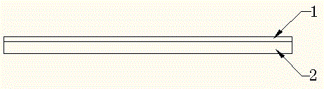
[0032] Example 1: Preparation of titanium steel-carbon steel single-sided composite panel

[0033] Blank making: Select TC4 titanium steel plate and Q345R carbon steel plate to assemble blanks according to the ratio of 1:4. The size of titanium steel plate is 40mm thick × 1500mm wide × 3000mm long, which is used as double plate 1; the size of carbon steel plate is 160mm thick × 1500mm wide × 3000mm long. As the base plate 2; clean the carbon steel plate and titanium steel plate until the metal base is seen; stack the double plate 1 and the base plate 2, send them to the press for compaction, and use 15mm thick carbon steel plates to spot weld around the stacked composite slabs Afterwards, submerged arc welding is used to package and weld, and the end of the welded composite slab blank is drilled to evacuate, and then the hole is closed to obtain a composite slab, such as figure 1 , the thickness of the composite slab is 200mm;

[0034] Heating: Send the qualified composite sl...

Embodiment 2

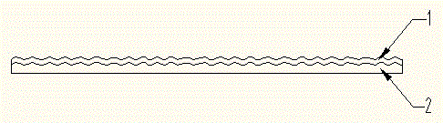
[0038] Embodiment 2: Preparation of copper plate-aluminum plate-copper plate double-sided composite board:

[0039] Blank making: Select T3 copper plate, LY2 aluminum plate and T3 copper plate to assemble billets according to the ratio of 1:3:1. The size of the aluminum plate is 120mm thick×800mm wide×3000mm long as the base plate 2, and the size of the copper plate is 40mm thick×800mm wide×3000mm long. as the upper cladding board 1 and the lower cladding board 1'; clean the aluminum board and two copper boards until the metal base is seen; stack the lower cladding board 1', the base board 2 and the upper cladding board 1, and send them to the press Machine compaction, spot welding around the stacked composite slabs to obtain composite slabs, such as Figure 6 , the thickness is 200mm;

[0040] Cleaning: Send the qualified composite slab to the cleaning equipment for cleaning;

[0041] Rough rolling: send the pickled composite slab to the composite rough rolling mill for rol...


PUM


Abstract

The invention discloses a method utilizing a herringbone ripple roller to roll a composite plate strip. The method is characterized in that a composite plate blank consisting of a basal plate and a composited plate is rolled into a herringbone ripple composite plate semi-finished product by a composite roughing mill provided with a herringbone ripple roller, and then, the herringbone ripple composite plate semi-finished product is rolled into a composite plate at a required thickness through a composite finishing mill provided with a flat roller. Herringbone ripples are symmetrically distributed relative to the radial central plane of the roller or symmetrically distributed relative to the axial central plane of the roller, and axial included angles between the herringbone ripples and the roller are 10-80 degrees. According to the invention, the problems that instant shock is produced during transverse ripple rolling and axial force drives the plate strip to shift during longitudinal ripple rolling are solved; and at the same time, the bonding area of the composite plate roughed is increased, so that bonding force between the basal layer and the composited layer is increased, and the compositing strength and compositing efficiency of the composite plate are greatly improved.

Description

technical field [0001] The invention belongs to the technical field of preparation of metal composite strips, and in particular relates to a method for rolling composite strips with herringbone corrugated rolls. Background technique [0002] Metal clad strip refers to a strip that is layered with another metal on one layer of metal to achieve the effect of saving resources and reducing costs without reducing the use effect (anti-corrosion performance, mechanical strength, etc.). Metal composite material technology can give full play to the respective advantages of component materials, realize the optimal allocation of component material resources, save precious metal materials, and achieve performance requirements that cannot be met by a single metal. It is mainly used in anti-corrosion, pressure vessel manufacturing, power construction, Petrochemical, pharmaceutical, light industry, automobile and other industries. Composite methods usually include explosive composite meth...

Claims


Application Information

Patent Timeline
IPC IPC(8): B21B1/38
CPCB21B1/38B21B2001/386
Inventor 李玉贵朱琳黄庆学张辽
Owner TAIYUAN UNIVERSITY OF SCIENCE AND TECHNOLOGY
Why Eureka
Try Eureka