High-speed hydraulic punching machine

A hydraulic press, high-speed technology, applied in the direction of presses, manufacturing tools, etc., can solve the problems of single function and low speed of hydraulic presses, and achieve the effect of improving safety performance, fast and efficient stamping production, and safe operation.

Active Publication Date: 2016-06-01
NANJING NINGDUAN HEAVY MACHINERY MFG CO LTD
View PDF7 Cites 5 Cited by
  • Summary
  • Abstract
  • Description
  • Claims
  • Application Information

AI Technical Summary

Problems solved by technology

[0003] The purpose of the present invention is to design a high-speed hydraulic punch that can achieve more than 60 times per minute and low-speed stretching for the problems of low speed and single function of the existing hydraulic punch.

Method used


Image

  • High-speed hydraulic punching machine
  • High-speed hydraulic punching machine
  • High-speed hydraulic punching machine

Examples


Embodiment 1

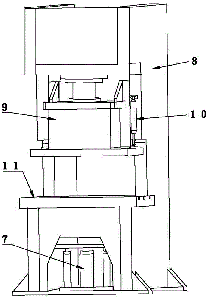
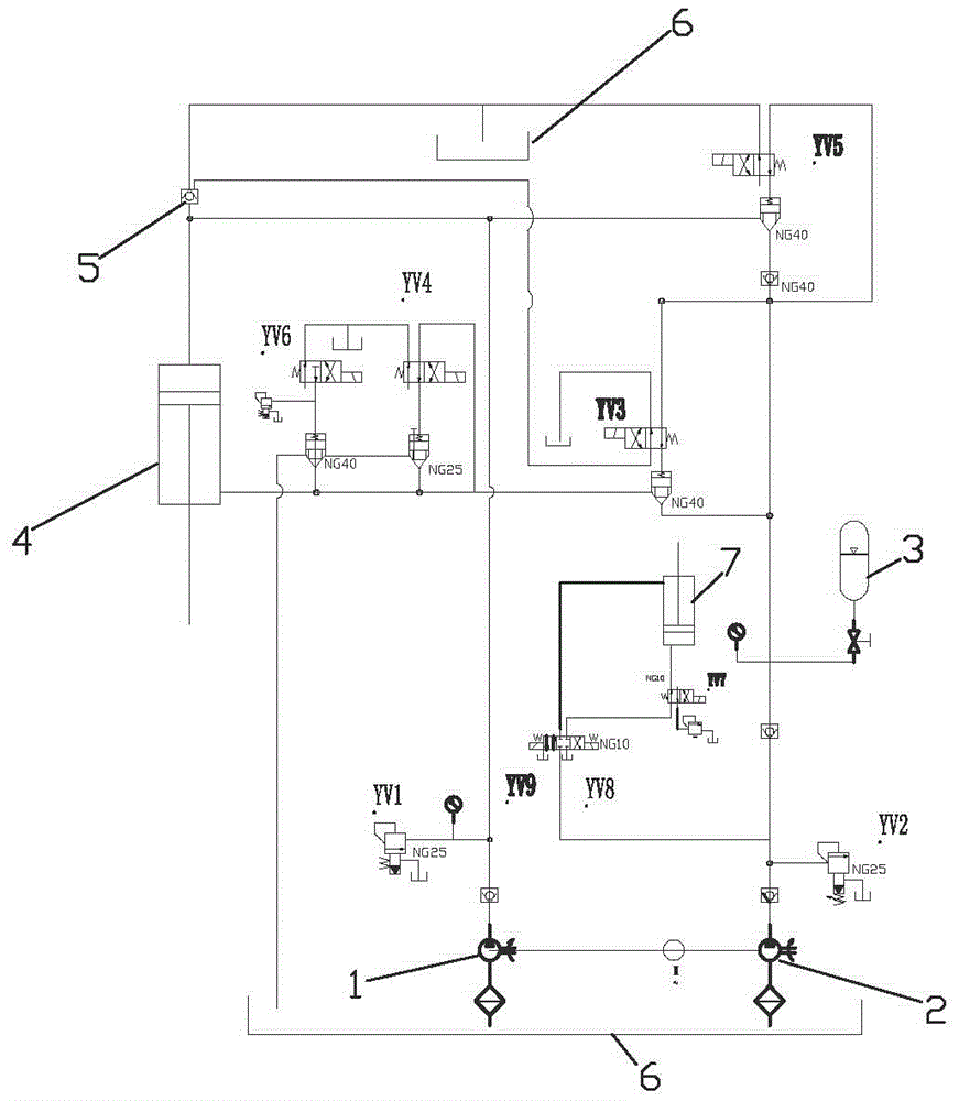
[0033] Such as figure 1 , 2 shown.

[0034] A high-speed hydraulic press, which includes a bed 8 and a slider 9, one end of an electronic ruler 10 is fixed on the bed 8, the other end is connected to the slider 9, the slider 8 is connected to the piston in the hydraulic cylinder 4, and the slider 8 Drive the piston down under the action of gravity and use gravity to directly absorb oil from the oil tank 6 to the working chamber. When the slider 9 goes down to the set position, the electronic ruler 10 drives the control system so that the double oil pump can quickly supply oil to the working chamber of the hydraulic cylinder at the same time to drive the piston. Drive the slider down quickly to realize high-speed stamping. When the slider goes down to the lower limit position, the electronic ruler 10 drives the control system again to stop one oil pump from supplying oil, so that the other oil pump and accumulator 3 can quickly supply oil to the oil return chamber of hydraulic...

Embodiment 2

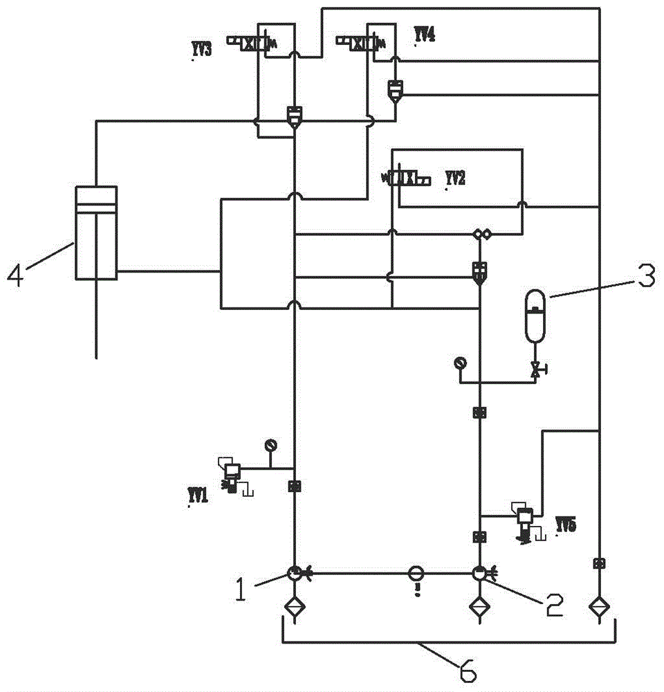
[0050] Such as figure 1 , 3 shown.

[0051] The difference between this embodiment and the first embodiment is that the hydraulic circuit is different. Since the pressure provided is relatively small (below 100 tons), its working principle is equivalent to that of the first embodiment, and the hydraulic circuit of the first embodiment can also be used. The schematic diagram of the hydraulic system of this embodiment is as follows image 3 shown.

[0052] The working process of this embodiment is:

[0053] 1. Standby.

[0054] All solenoid valves in the system are in a de-energized state. At this time, the hydraulic oil output by the oil pump is directly returned to the oil tank through the YV1 and YV2 electromagnetic overflow valves, that is, the hydraulic system is in a standby state.

[0055] 2. Fast down the slider.

[0056] When the slider is fast down, the YV1, YV2, YV3, YV5 solenoid valves are energized at the same time. Therefore, the hydraulic oil output by the...


PUM


Abstract

A high-speed hydraulic punching machine comprises a machine bed and a sliding block and is characterized in that one end of an electronic ruler is fixed to the machine bed, the other end of the electronic ruler is connected to the sliding block, the sliding block is connected to a piston of a hydraulic cylinder and drives the piston to move downwards under the gravity effect, oil is directly sucked into a working chamber from an oil tank through the gravity, when the sliding block moves downwards to the set position, the electronic ruler drives a control system to enable double oil pumps to fast supply oil to the working chamber of the hydraulic cylinder simultaneously for driving the piston to drive the sliding block to fast move downwards for realizing high-speed punching, when the sliding block moves downwards to the lower limit position, the electronic ruler drives the control system again to enable one oil pump to stop supplying the oil, and the other oil pump and an energy accumulator fast supply oil to an oil return chamber of the hydraulic cylinder for enabling the piston to fast return to another cycle. The high-speed hydraulic punching machine has the advantages of being stable, safe, mute, friendly to environment, practical, wide in application range, easy and convenient to operate, easy to control and compact in structure, saving the energy and reducing emission, and work-pieces are attractive.

Description

technical field [0001] The invention relates to a kind of mechanical equipment, especially a stamping equipment, in particular to a multifunctional high-speed hydraulic punching machine capable of both high-speed stamping and low-speed stretching. Background technique [0002] At present, most of the punching machines are rotary mechanical structures, which have high noise, low safety factor, complex structure, easy damage, and single function, so they can only be used for punching. Stamping capacity is limited. The hydraulic system has the advantages of low noise, stable operation, simple structure and large tonnage. However, due to the design limitation of the hydraulic system, the speed of the existing hydraulic punching machine cannot be increased. Generally, it is more than ten or twenty times per minute, and the efficiency is not high. Therefore, designing a high-speed hydraulic press with a large tonnage (above 100 tons) to achieve high-speed stamping of more than 60...

Claims


Application Information

Patent Timeline
Patent Type & Authority Applications(China)
IPC IPC(8): B30B15/16B30B15/22B30B15/28
CPCB30B15/166B30B15/22B30B15/28
Inventor 王翀
Owner NANJING NINGDUAN HEAVY MACHINERY MFG CO LTD
Why Eureka
Try Eureka