
Fan shroud protecting device

A protective device and shielding technology, which is applied in the direction of engine components, machine/engine, engine cooling, etc., can solve the problems of hindering the normal passage of airflow, poor dustproof effect of fan shields, etc., and achieve the effect of enhancing the dustproof effect

Inactive Publication Date: 2016-06-01
SHANDONG HUALIAN MINING
View PDF0 Cites 1 Cited by
  • Summary
  • Abstract
  • Description
  • Claims
  • Application Information

AI Technical Summary

Problems solved by technology

[0004] One, the dustproof effect of the existing fan guard is relatively poor;
[0005] Second, after long-term use of the fan guard, more dust will adhere to it, which will hinder the normal passage of airflow

Method used


Image

  • Fan shroud protecting device

Examples


Embodiment 1

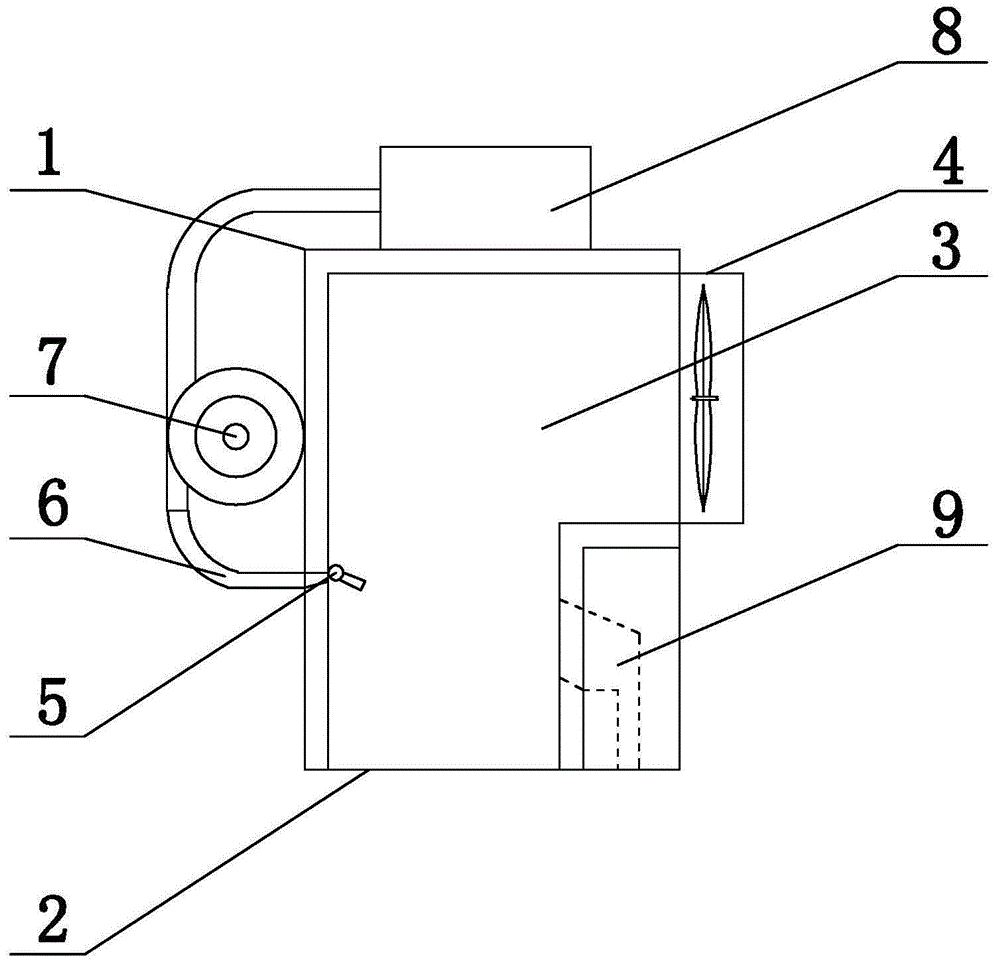
[0020] Embodiment 1: as figure 1 As shown, the protective device for the fan guard of the present invention includes a housing 1, the housing 1 is provided with an air inlet 2, and the housing 1 is provided with an air duct 3, one end of the air duct 3 is connected to the air inlet 2, and the other end is connected to the fan The shield 4 is connected, and the side of the air duct 3 is provided with a water spray port 5, and the water spray port 5 is connected to the drain end of the water pump 7 on the shell 1 through the water pipe 6, and the pumping end of the water pump 7 is connected to the water tank 8, and the air duct 3 The other side is provided with a drainage channel 9, and the water spray port 5 is aligned with the opening of the water spray channel 9.

Embodiment 2

[0021] Embodiment 2: On the basis of the structure described in Embodiment 1, the water nozzle 5 is inclined downward from the horizontal direction by 20°-45°, the top of the air duct 3 is provided with a turbine, and the fins of the turbine are provided with a sponge layer.

Embodiment 3

[0022] Embodiment 3: On the basis of the structure described in Embodiment 2, a filter screen is provided at the air inlet 2, and the filter screen is located directly below the water spray port.

[0023] Operation steps and working principle:

[0024] In the protective device for the fan guard, the wind enters the air duct 3 from the air inlet 2, and first passes through the water wall formed by a plurality of water spray outlets 5 arranged side by side. Because the water has hydraulic pressure, the water will not be taken away by the air flow, but the air flow When passing through the water wall, the particles in the air and the substances easily soluble in water will be taken away by the water flow with hydraulic pressure, enter the drainage channel 9 together with the water flow, and be discharged by the drainage channel 9, even if the impurities cannot be washed in by the water flow Drain channel 9, also can not be continued to carry by air-flow and falls because of being...


PUM


Abstract

The invention provides a fan shroud protecting device and belongs to the field of engine fan anti-dust devices. The fan shroud protecting device comprises a shell which is provided with an air inlet. An air duct is arranged in the shell. One end of the air duct is connected with the air inlet, and the other end of the air duct is connected with a fan shroud. One side of the air duct is provided with a water spraying opening, and the water spraying opening is connected with the water draining end of a water pump on the shell through a water pipe. The water suction end of the water pump is connected to a water tank. The other side of the air duct is provided with a water draining channel. The water spraying opening is aligned with an opening of the water draining channel. The dust preventing effect of the fan shroud can be improved, and heavy accumulation of dust is avoided.

Description

technical field [0001] The invention provides a protective device for a fan guard, which belongs to the field of dust-proof devices for engine fans. Background technique [0002] The engine will generate a lot of heat when it is working. At this time, the fan is required to cool it through the water tank, and the fan will often bring in many impurities or foreign objects due to the airflow formed during the working process. If things go on like this, the shaft of the fan will be damaged due to lack of oil. As a result, the power required for its rotation becomes larger and larger. When the fan cannot rotate, it may even burn out the fan motor due to excessive power. After the motor burns out and the fan does not rotate, the engine temperature cannot be effectively reduced, and the water tank will be damaged by the engine. The temperature is too high to cause "boiling phenomenon". [0003] Current prior art defect is: [0004] One, the dustproof effect of the existing fan g...

Claims


Application Information

Patent Timeline
Patent Type & Authority Applications(China)
IPC IPC(8): F01P5/06F01P11/06
Inventor 张志利
Owner SHANDONG HUALIAN MINING
Learn More