Centrifugal supercharger

A supercharger, centrifugal technology, applied in the field of superchargers, to achieve the effect of improving product life, stable and safe mechanical transmission, and improving overall efficiency

Inactive Publication Date: 2016-06-01
北京斯特透平机械有限公司
View PDF11 Cites 2 Cited by
  • Summary
  • Abstract
  • Description
  • Claims
  • Application Information

AI Technical Summary

Problems solved by technology

[0007] Although the products of the above-mentioned inventions have been applied in industrial production, there is still room for improvement in some aspects of the product, especially the main parts of the product, namely the rotor and the working wheel (i.e. the ...

Method used


Image

  • Centrifugal supercharger
  • Centrifugal supercharger

Examples


Embodiment Construction

[0017] Hereinafter, the centrifugal supercharger of the present invention will be further described in detail with reference to the drawings and specific embodiments.

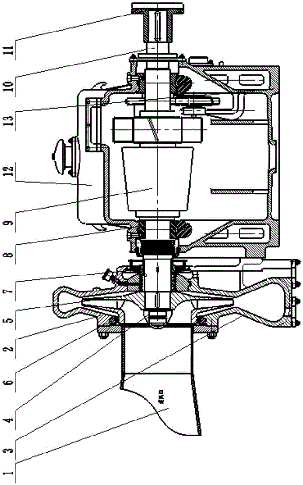
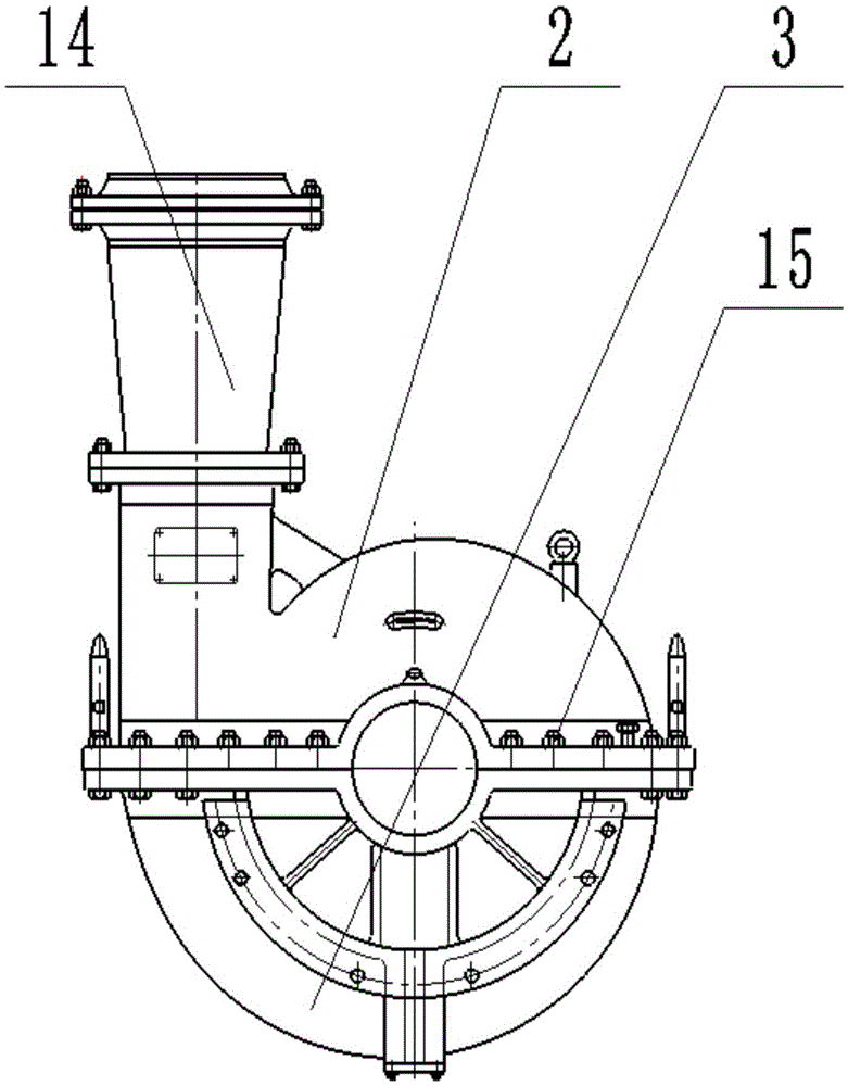
[0018] figure 1 It is a front cross-sectional view of the centrifugal supercharger of the present invention, as shown in the figure. The centrifugal supercharger includes the air inlet cylinder 1, the upper volute 2, the lower volute 3, the shaft end nut 4, the impeller 5, the sealing assembly 6, the exhaust wheel 7, the bearing 8, the pinion shaft 9, and the power input shaft 10. , Coupling 11, upper machine cover 12, lower machine base 13. The impeller 5 and the exhaust wheel 7 are installed on the pinion shaft, the impeller is fixed by the shaft end nut 4, the installed pinion shaft is placed on the lower frame with bearing support, and the power input shaft 10 passes through a large gear and a small gear. The gear shaft is combined, and the upper machine cover and the lower machine base are installed.

[0019]...


PUM


Abstract

A centrifugal supercharger comprises a power input shaft, a large gear, a small gear shaft, a shaft sleeve, an impeller, an exhaust wheel, a bearing, a coupler, a volute casing and the like. The centrifugal supercharger is characterized in that the large gear is mounted on the power input shaft and is engaged with the small gear shaft through inclined teeth, and through an inclined gear, mechanical transmission will be more stable and safer; the impeller, the exhaust wheel, the shaft sleeve, a shaft head nut and other parts are mounted on the small gear shaft to form a main component of the centrifugal supercharger, and the main component is a rotor of the centrifugal supercharger; and the exhaust wheel is arranged on the outer side of a sealing device at the contact position of the impeller and the volute casing of the supercharger. A casting structure is adopted in a machine shell, and an X-shaped structural manner is adopted in an upper volute casing body and a lower volute casing body; a stainless steel closed type impeller is adopted as the impeller, a blade manner of a backward bending structure is adopted in blades, the blades are alternative in length, and the number of the blades is 11; and according to the centrifugal supercharger, the working efficiency is greatly improved, the manufacturing and maintaining cost is greatly reduced, the service life of the supercharger is greatly prolonged, and the centrifugal supercharger is unanimously praised.

Description

Technical field [0001] The invention belongs to the technical field of superchargers, and particularly relates to a centrifugal supercharger used to increase the pressure of gas in the technical field of chemical engineering to complete subsequent processes. Background technique [0002] At present, in the petrochemical industry, the centrifugal supercharger is an important equipment of the catalytic device, which is used to pressurize the main air from the main fan, and part of the pressurized main air is used as the fluidized air of the external extractor. The other part enters the bottom of the standpipe of the external heat extractor, as the lifting air for the catalyst in the external heat extractor to return to the dense phase bed of the regenerator, providing driving force for countercurrent regeneration. [0003] At present, most of the turbochargers used in the petrochemical industry include power input shafts, power output shafts, impellers, seals and shells. The power in...

Claims


Application Information

Patent Timeline
IPC IPC(8): F04D17/10F04D29/28F04D29/30F04D29/10F04D29/42F04D29/02
CPCF04D17/10F04D29/023F04D29/10F04D29/284F04D29/30F04D29/4206
Inventor 石雪松
Owner 北京斯特透平机械有限公司
Why Eureka
Try Eureka