Object three-dimensional shape measurement method using single pixel detector and device thereof

A technology of three-dimensional shape and measurement method, which is applied in the direction of measuring devices, optical devices, instruments, etc., and can solve problems such as long measurement time, low measurement accuracy, and large number of measurements

Active Publication Date: 2016-06-01
JINAN UNIVERSITY
View PDF4 Cites 14 Cited by
  • Summary
  • Abstract
  • Description
  • Claims
  • Application Information

AI Technical Summary

Problems solved by technology

[0004] The purpose of the present invention is to use a single-pixel detector for three-dimensional shape measurement, and to sol...

Method used


Image

  • Object three-dimensional shape measurement method using single pixel detector and device thereof
  • Object three-dimensional shape measurement method using single pixel detector and device thereof
  • Object three-dimensional shape measurement method using single pixel detector and device thereof

Examples


Embodiment 1

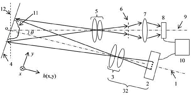
[0056] image 3 As shown in the device schematic diagram of the embodiment, a digital projector is used as the projector 32, and a spatial frequency is 3 lines per millimeter, and the size is 50.0 2 A square millimeter grating is used as a planar grid device 6 and a photocell is used as a single pixel photodetector 8 . The imaging lens group 5 adopts a focal length f 1 200.0 mm single lens, distance L from plane 12 1 1200.0 mm, distance L from grating 6 2is 240.0. The distance between the lens 5 and the plane 12 and the grating 6 satisfies the object-image relationship, that is, the grating 6 is placed on the image plane of the lens 5 against the plane 12 . The optical centers of the lens 5 and the signal collection lens 7 are on the same axis, and the included angle θ between this axis and the optical axis of the digital projector 32 is 17 degrees. Assuming that the range of the light field illumination target object is represented by discretized pixels, the size is an M...

Embodiment 2

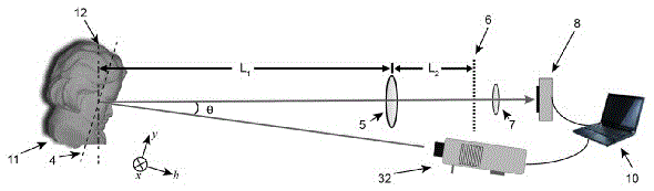
[0058] In order to reduce the number of measurements, we first pre-estimated the center frequency value of the first-order component of the Fourier spectrum of the deformed fringe pattern according to the frequency of the grating. Experimental device such as image 3 Shown, where the focal length f of the lens (5) 1 =200mm, distance L from lens (5) to plane (12) 1 =1200 mm, the distance L from the lens (5) to the grating (6) 2 =240 millimeters, the angle between plane (4) and plane (12) is 17 °. According to the imaging law, it can be known that the magnification of the imaging system of the detection optical path is μ=L 2 -1 L 1 =5, that is, the 5 times larger image formed by the grating sheet on the plane (12). The spatial frequency of the grating sheet is 3 lines per millimeter. According to the scaling relationship, the spatial frequency of the fringe image of the grating on the reference surface is 3 / 5=0.6 lines per millimeter. The physical area for imaging is 138...

Embodiment 3

[0060] We use a computer to generate a series of cosine distribution patterns of frequencies, and each frequency only contains three patterns whose initial phases are -π / 2, 0, and π / 2, and the corresponding response values ​​are expressed as: D 13 (f x ,f y ), D 23 (f x ,f y ), D 33 (f x ,f y ). After the center frequency of the primary component is estimated, the frequency spectrum of the primary component is collected in a circular window near the center frequency. According to the formula:

[0061] C(f x ,f y )={[2D 23 (f x ,f y )-D 13 (f x ,f y )-D 33 (f x ,f y )]+j·[D 33 (f x ,f y )-D 13 (f x ,f y )]}

[0062] Calculate the Fourier spectral coefficients in the window to obtain the first-order component of the Fourier spectrum And perform a two-dimensional discrete inverse Fourier transform, then find its argument (phase), and then subtract the linear phase 2πf 0y y, the modulation phase distribution reflecting the surface topography of the obj...


PUM


Abstract

The invention discloses an object three-dimensional shape measurement method using a single pixel detector and a device thereof. A structural light field generator generates a series of cosine distribution lighting light fields which light target objects in turn through a lighting lens group; an imaging lens group performs imaging of the lighted target objects to a plane grating device so as to form target object images modulated by the plane grating device; the single pixel detector receives light signals of the modulated target object images in turn according to different lighting light fields and outputs electric signal response values in turn, and calculates the Fourier spectrum primary component I<1><~> of the modulated target object images by utilizing a series of electric signal response values; modulation phase distribution of the target object images is calculated through I<1><~>, and difference value calculation is performed on modulation phase distribution of the target object images and modulation phase distribution of reference plane plate images so that phase difference distribution deltaphi(x,y) is obtained; and then the measured values of height distribution h(x,y) of the surface shape of the target objects to be measured are obtained by utilizing the corresponding relation of phase difference and height.

Description

technical field [0001] The invention relates to the technical fields of optical imaging and optical measurement, in particular to an optical three-dimensional shape measurement method using a single-pixel detector. Background technique [0002] Single-pixel imaging technology uses a photodetector (such as a photodiode) that has no spatial resolution capability to perform multiple sampling in time to complete the acquisition of image information. Currently widely used two-dimensional array silicon photodetectors (such as CCD and CMOS) are only suitable for detection in the visible light band. However, certain fields such as biomedicine and military must use non-visible light source illumination for imaging, which has led to the demand for single-pixel imaging technology with wider spectral response. This is why single-pixel imaging technology has become a hot research topic in the past decade. [0003] For single-pixel 2D imaging, published solutions include ghost imaging [...

Claims


Application Information

Patent Timeline
IPC IPC(8): G01B11/25
CPCG01B11/254
Inventor 钟金钢张子邦
Owner JINAN UNIVERSITY
Why Eureka
Try Eureka