
Plasma processing equipment

A processing equipment and plasma technology, applied in the direction of discharge tubes, electrical components, circuits, etc., can solve the problems of poor etching uniformity, residual corners or arc structures, and difficulty in forming triangular shapes, so as to reduce density and increase The thickness of the sheath, the effect of improving the uniformity of etching

Active Publication Date: 2016-06-01
BEIJING NAURA MICROELECTRONICS EQUIP CO LTD
View PDF6 Cites 8 Cited by
  • Summary
  • Abstract
  • Description
  • Claims
  • Application Information

AI Technical Summary

Problems solved by technology

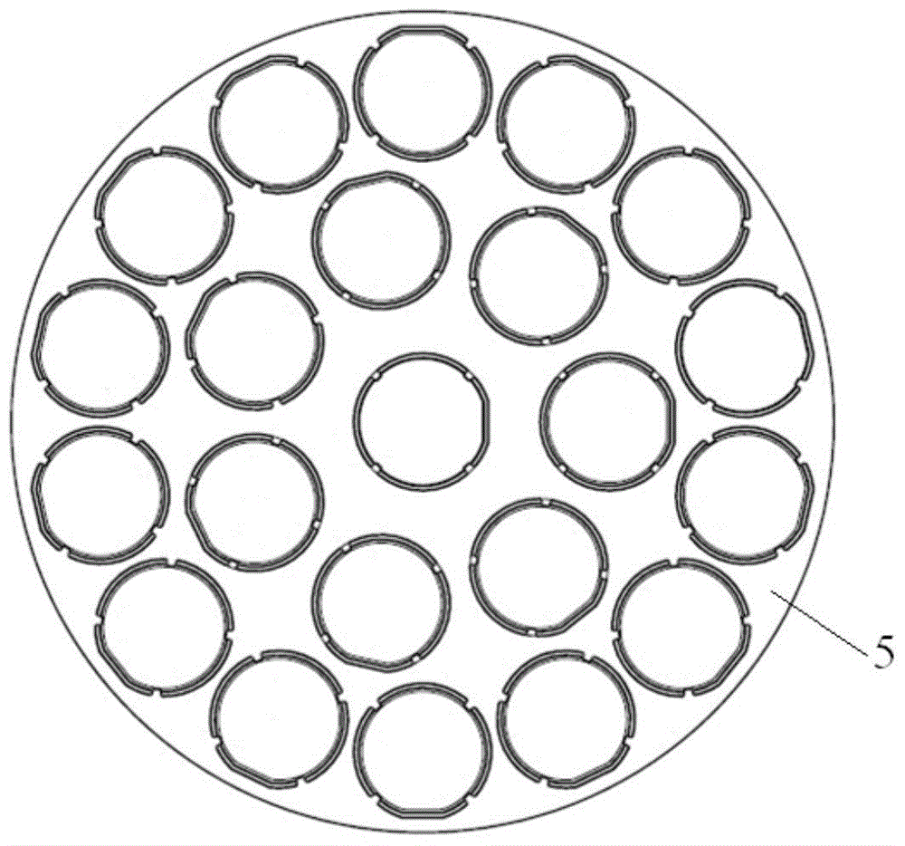
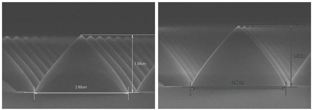
Wherein, the etching height of the outer ring wafer is 1.58um, and the etching height of the central wafer is 1.69um. It can be seen that the closer to the center of the tray 5, the higher the height of the etching profile of the wafer, thereby the etching uniformity is higher. Difference
Moreover, the etched profile of the central wafer often leaves corners or arc structures, making it difficult to form an ideal triangular shape

Method used


Image

  • Plasma processing equipment
  • Plasma processing equipment
  • Plasma processing equipment

Examples


Embodiment Construction

[0034] In order for those skilled in the art to better understand the technical solutions of the present invention, the plasma processing equipment provided by the present invention will be described in detail below in conjunction with the accompanying drawings.

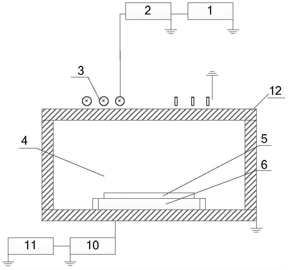
[0035] The plasma processing equipment provided by the present invention includes a reaction chamber, a base for carrying workpieces to be processed, and a radio frequency antenna device for exciting the reaction gas in the reaction chamber to form plasma. The radio frequency antenna device includes an inductance coil, an electrode The plate group and the radio frequency source, wherein the inductance coil and the electrode plate group are connected in parallel with each other and are electrically connected to the radio frequency source. When the radio frequency source is turned on, it simultaneously loads radio frequency power to the inductance coil and the electrode plate group, and the inductance coil adopts inducti...


PUM


Abstract

The invention provides plasma processing equipment, and the equipment comprises a reaction cavity, a substrate for carrying a machined workpiece, and a radio frequency antenna device. The radio frequency antenna device comprises an inductive coil, an electrode plate group, and a radio frequency source. The inductive coil and the electrode plate group are in parallel connection, and are electrically connected with the radio frequency source. Moreover, the inductive coil and the electrode plate group are disposed at the top of the reaction cavity, and are respectively corresponding to different positions of the substrate. The equipment employs the electrode plate group to generate plasma at the same time on the basis of employing the inductive coil to generate plasma, and can achieve the adjustment of the distribution density of plasma at different positions, so as to enable the etching results of various types of machined workpieces on the substrate to be uniform, thereby improving the etching uniformity.

Description

technical field [0001] The present invention relates to the technical field of semiconductor manufacturing, in particular to a plasma processing equipment. Background technique [0002] With the rapid development of electronic technology, people have higher and higher requirements for the integration of integrated circuits, which requires enterprises that produce integrated circuits to continuously improve the processing capacity of semiconductor wafers. Currently, in processes such as conventional semiconductor manufacturing, various types of plasma processing equipment have been used, for example, capacitively coupled plasma (CCP) type, inductively coupled plasma (ICP) type, and surface wave or electron cyclotron resonance plasma (ECR) type and so on. Among them, the equipment that uses capacitive coupling to generate plasma has a simple structure and is easy to generate large-area uniformly distributed plasma, which is suitable for etching dielectric and other types of f...

Claims


Application Information

Patent Timeline
IPC IPC(8): H01J37/32
Inventor 韦刚刘利坚李东三李兴存
Owner BEIJING NAURA MICROELECTRONICS EQUIP CO LTD
Learn More