

Thermoelectric battery with series-wound electric leg structure
A technology of thermoelectric battery and electric leg, applied in the field of thermoelectric battery, can solve problems such as difficulty in obtaining a large temperature gradient, and achieve the effect of being beneficial to popularization and application
- Summary
- Abstract
- Description
- Claims
- Application Information
AI Technical Summary
Problems solved by technology
Method used
Image

Examples
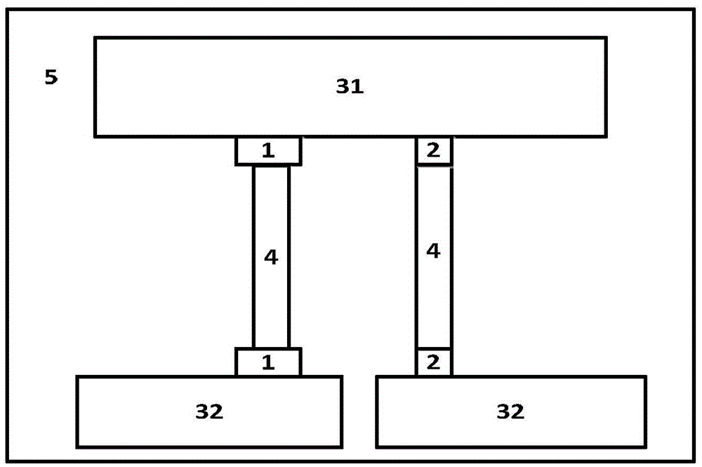
Embodiment 1
[0017] 1. Choose a quartz plate as the substrate;
[0018] 2. Using thermal evaporation method to prepare two bismuth tellurium selenium thermoelectric films with a width of 5 mm and a length of 1 cm on the substrate, with an intermediate distance of 1 cm;
[0019] 3. Use the same method to prepare two bismuth, antimony, tellurium thermoelectric films with a length of 5 mm and a length of 1 cm, with an intermediate distance of 1 cm;
[0020] 4. Prepare the copper film connected to the bismuth-tellurium-selenium film and the copper film connected to the bismuth-antimony-tellurium film by the thermal evaporation method;
[0021] 5. The cold end and hot end electrodes are prepared by the evaporation method.
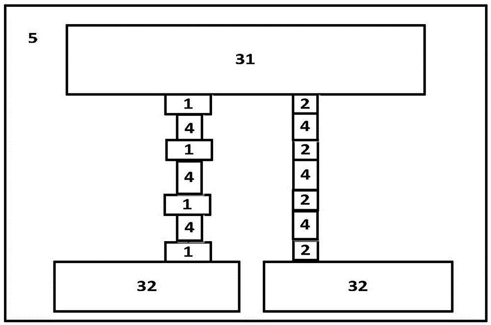
Embodiment 2
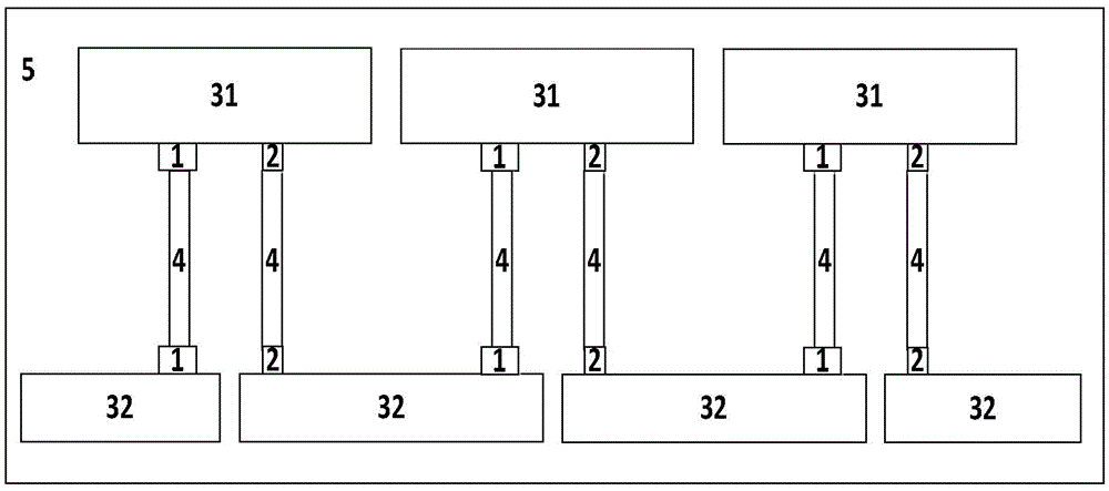
[0022] Example 2 (attached image 3 )
[0023] 1. Select polyimide film as flexible substrate
[0024] 2. Using thermal evaporation method to prepare two bismuth selenide thermoelectric films with a width of 5 mm and a length of 1 cm on the substrate, with an intermediate distance of 1 cm;
[0025] 3. Use the same method to prepare two antimony telluride thermoelectric films with a length of 5 mm and a length of 1 cm, with an intermediate distance of 1 cm;
[0026] 4. Prepare the copper film connected with the bismuth selenide film and the copper film connected with the antimony telluride film by the thermal evaporation method;
[0027] 5. The cold end and hot end electrodes are prepared by the evaporation method.
Embodiment 3
[0029] 1. Choose a quartz plate as the substrate;
[0030] 2. Using molecular beam epitaxy on the substrate to prepare two silicon germanium thermoelectric films with a width of 5 mm and a length of 1 cm, with an intermediate distance of 1 cm;
[0031] 3. The laser flash method is used to prepare two ferrosilicon thermoelectric films with a length of 5 mm and a length of 1 cm, with an intermediate distance of 1 cm;
[0032] 4. Prepare the copper film connected to the silicon-germanium film and the copper film connected to the ferrosilicon film by the thermal evaporation method;
[0033] 5. The cold end and hot end electrodes are prepared by the evaporation method.
PUM
| Property | Measurement | Unit |
|---|---|---|
| Width | aaaaa | aaaaa |
| Length | aaaaa | aaaaa |
| Length | aaaaa | aaaaa |
Abstract
Description
Claims
Application Information