
Organism surface electrical signal detecting electrode array

A technology for detecting electrodes and electrical signals, used in diagnostic recording/measurement, medical science, sensors, etc., can solve problems such as inability to guarantee the consistency of test conditions, damage to the tested organism, and interference signal characteristics, and achieve high-throughput testing. and the effects of storage, efficient detection, and noise reduction

Active Publication Date: 2016-06-08
ZHENJIANG COLLEGE
View PDF10 Cites 2 Cited by
  • Summary
  • Abstract
  • Description
  • Claims
  • Application Information

AI Technical Summary

Problems solved by technology

[0003] 1. The signal amplitude is very weak, such as nerve potential, electromyographic signal, etc., which cannot be directly obtained by conventional detection methods and equipment. If an amplifier is introduced, it will bring great interference and make the original signal characteristics be submerged by noise signals
[0004] 2. Most of the acquisition of existing bioelectrical signals uses microelectrodes, and in order to obtain weak signals such as neural electrical signals and biological trigger signals, in order to avoid noise, invasive detection methods (such as needle electrodes, etc.) are used, not only for the measured Mobs deal extra damage and introduce new noise
[0005] 3. The biological signal is a non-stationary signal with strong randomness. According to different test conditions and requirements, the state of the electrode and the detection method need to be changed in time
[0006] 4. Due to the characteristics of organisms and biological signals, the existing detection electrodes cannot guarantee the consistency of test conditions

Method used


Image

  • Organism surface electrical signal detecting electrode array
  • Organism surface electrical signal detecting electrode array

Examples


Embodiment Construction

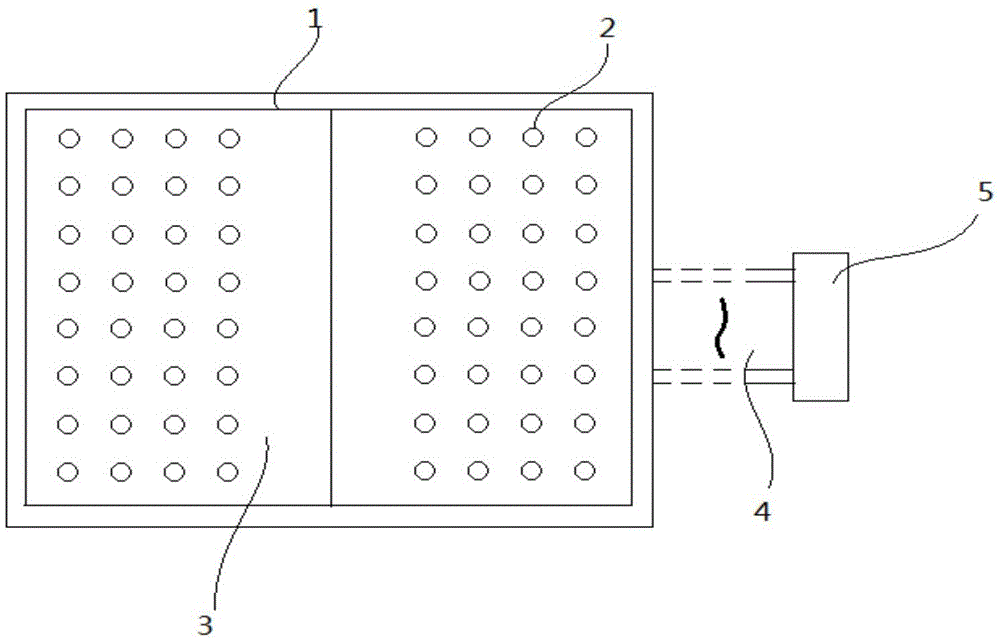
[0032] Below in conjunction with accompanying drawing, describe in detail, as figure 1 , figure 2 As shown, the electrode carrier 3 of the flexible printed circuit board is adopted, and the electrode carrier 3 adopts double-sided printed circuit wiring, and the electrode points 2 arranged in an array are arranged on the electrode carrier 3, and the electrode point array of the electrode carrier 3 is left and right Divide into 2 areas on average, and use 2-3mm printed circuit wiring as the ground wire 1 for fully enclosed surrounding, and set the pad 6 on the electrode point 2, and fill the pad with solder 7 to achieve soldering 7 and the electrical connection of the pad 6, the surface of the solder is plated with silver or silver chloride 8, and each electrode point 2 pad 6 is electrically connected to the The common interface end 5, the common interface end 5 is connected to the excitation source and the signal collector through a shielded cable, the common interface end 5 ...


PUM


Abstract

An organism surface electrical signal detecting electrode array comprises an electrode carrier of a flexible printed circuit board, wherein the electrode carrier adopts double-sided printed circuit wiring; electrode points in array arrangement are arranged on the electrode carrier; the electrode point array of the electrode carrier is averagely partitioned into two zones left and right, and the two zones use 2-3 mm printed circuit PCB wires as ground wires respectively to form full closure; miniature heating resistors are also arranged on the electrode points; each miniature heating resistor is provided with two pins; one pin is connected to a common interface end through PCB wiring on the side opposite to a welding pad; the other pin is connected to a 5V power supply through the PCB wiring on the side opposite to the welding pad; the miniature heating resistor is connected with the welding pad and welding tin in an insulated way; the miniature heating resistor body is embedded into the welding tin. The organism surface electrical signal detecting electrode array can keep the temperature of each electrode point controllable, so that the temperature error is reduced.

Description

technical field [0001] The invention relates to a design method of a detection electrode array suitable for weak electrical signals on the surface of a living body. Background technique [0002] The detection of electrical signals on the surface of living organisms has always been one of the difficult problems in the field of biomedicine. The detection of electrical signals on the surface of living organisms has the following problems: [0003] 1. The signal amplitude is very weak, such as nerve potential, electromyographic signal, etc., which cannot be directly obtained by conventional detection methods and equipment. If the amplifier is introduced, it will bring great interference and make the original signal characteristics be submerged by noise signals. [0004] 2. Most of the acquisition of existing bioelectrical signals uses microelectrodes, and in order to obtain weak signals such as neural electrical signals and biological trigger signals, in order to avoid noise, i...

Claims


Application Information

Patent Timeline
IPC IPC(8): A61B5/04
CPCA61B2560/0462A61B2562/0209A61B2562/182A61B2562/222A61B5/24
Inventor 王宇航黄岑宇
Owner ZHENJIANG COLLEGE
Learn More